2920 Float & Tape Transmitter
4 Wiring
26
Installation and Operations Manual
Contact Outputs
When specified by the order code, 4 contact outputs are provided. These are software driven
“Normally Open/Closed” outputs. The outputs can be configured using a Bi-Phase Mark Host,
through the local display interface, or a computer running ViewRTU. They can be set to trigger
(alarm lights, horns, and so on) for temperature or level alarms.
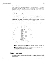
I.S. HART Junction Box
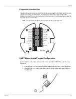
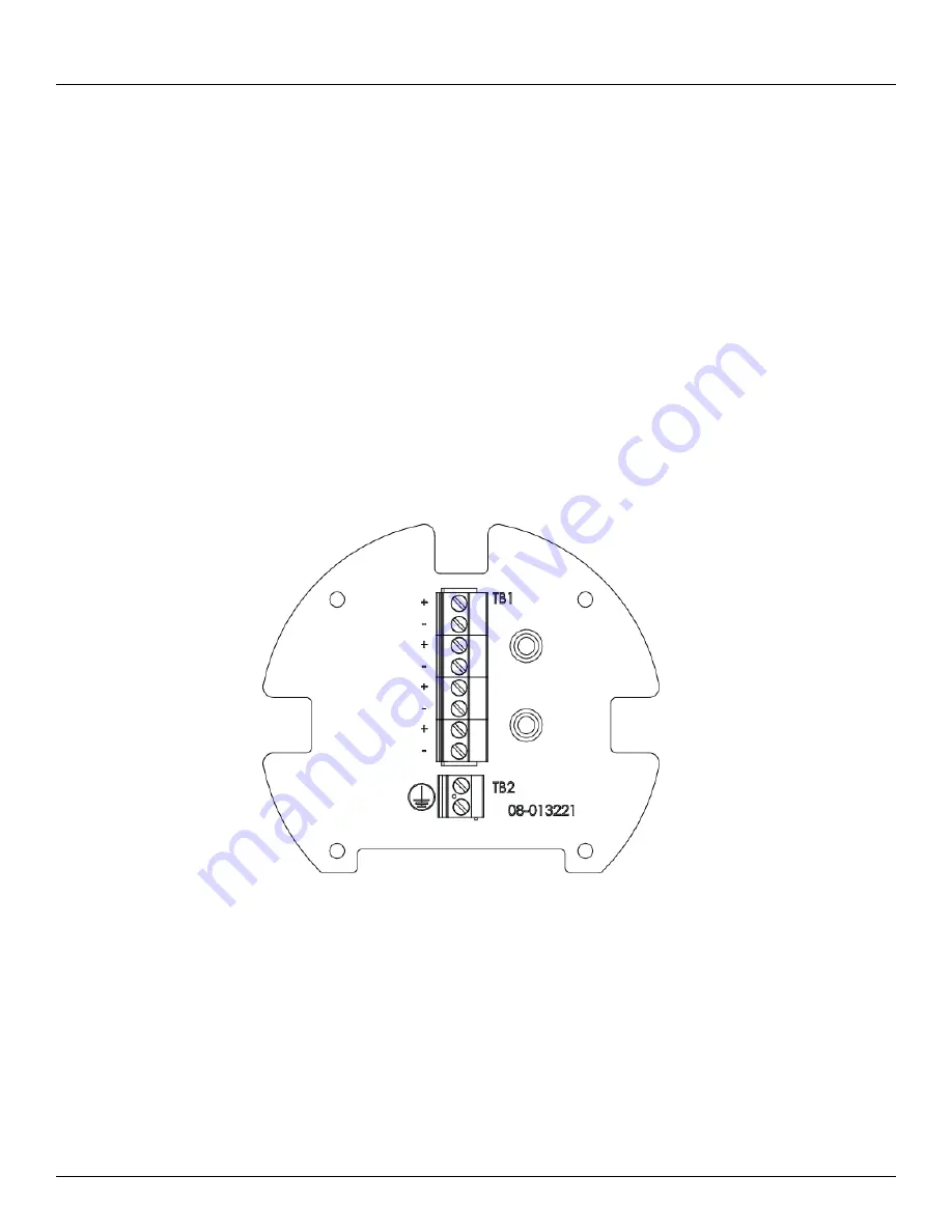
The I.S. HART junction box provides 8 intrinsically safe terminals using pluggable terminal
connectors and includes 2 earth ground terminals. The 8 terminals are used to connect HART
SMART transmitters. The terminals are l for positive HART connections and – for
negative HART connections. The terminals are grouped into 4 + and – terminals so each HART
transmitter can easily be connected individually. The following figure shows the typical I.S.
HART Junction Box terminal board.
Refer to the associated intrinsically safe apparatus control drawing 28-013355, Appendix D.
Note The I.S. HART junction box is labeled with a light blue sticker. It is intrinsically safe
and may be opened while energized.
Note An Ex d HART/Non-I.S. HART option is available on models without the I.S. HART
option on the L & H terminals in the main junction box.
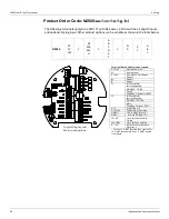
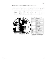
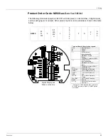
Wiring Diagrams
Following are the wiring diagrams for each variant of the 2920. These diagrams are categorized
by order codes.
Summary of Contents for 2920
Page 2: ......
Page 16: ...2920 Float Tape Transmitter 1 Introduction 6 Installation and Operations Manual...
Page 114: ...2920 Float Tape Transmitter 6 Bi Phase Mark 104 Installation and Operations Manual...
Page 120: ...2920 Float Tape Transmitter 7 MODBUS 110 Installation and Operations Manual...
Page 126: ...2920 Float Tape Transmitter 9 L J TankWay 116 Installation and Operations Manual...
Page 158: ...2920 Float Tape Transmitter 14 Ordering Information 148 Installation and Operations Manual...
Page 193: ......

