4 Wiring
Varec, Inc.
47
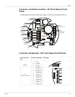
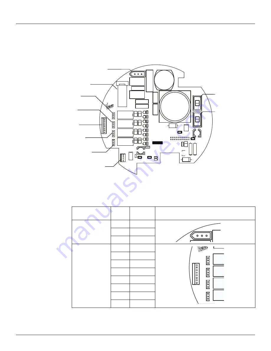
Connector and Switch Locations: AC Power Supply Circuit
Board
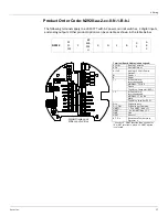
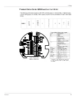
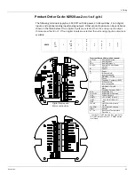
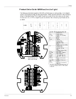
The following figure shows the AC Power Supply circuit board as viewed from the top.
Connector Assignments: AC Power Supply Circuit Board
R8
+
D9
D5
C6
C5
-
Q3
U1
R5
D10
NO
R6
J2
NC
D6
Q4
Q2
K1
L1
D4
R7
C1
C2
Q1
L
C3
Q5
Varec, Inc.
K2
G
K3
40-65
SW2
VAC
D7
R10
D8
K4
R2
0V
C4
5V
R1
R3
S3
Rev 071204
+48V
S
GT2
J1
D2
D3
J8
S2
J3
B-
Assembly 012836
S1
R11
NO
S
J6
NC
N
Q7
NO
J5
NC
Q8
R9
R4
Q6
NO
J4
NC
D1
GT1
T1
110/220
R12
Serial No
110VAC
VAC
R14
220
Q9
R13
SW1
VAC
Z2
Z1
F1
8
1
1
4
SW1
110 or 220 VAC
SW2
High or Low
AC Voltage
J1
AC Power In
F1
AC Power Fuse
(80 mA)
J6
NO/NC Jumper
for Output 4
J5
NO/NC Jumper
for Output 3
J4
NO/NC Jumper
for Output 2
J3
Discrete Outputs
1 - 4
J2
NO/NC Jumper
for Output 1
J8
Discrete Inputs
1 & 2
Connector/Func-
tion
Terminal Assignment Illustration
J1
AC Power
L
Line
N
Neutral
G
Ground
J3
Discrete Outputs (4)
1
Output 1 A
2
Output 1 B
3
Output 2 A
4
Output 2 B
5
Output 3 A
6
Output 3 B
7
Output 4 A
8
Output 4 B
L
G
J1
N
NO
J2
NC
K1
K2
K3
K4
NO
J6
NC
NO
J5
NC
NO
J4
NC
J3
8
1
Summary of Contents for 2920
Page 2: ......
Page 16: ...2920 Float Tape Transmitter 1 Introduction 6 Installation and Operations Manual...
Page 114: ...2920 Float Tape Transmitter 6 Bi Phase Mark 104 Installation and Operations Manual...
Page 120: ...2920 Float Tape Transmitter 7 MODBUS 110 Installation and Operations Manual...
Page 126: ...2920 Float Tape Transmitter 9 L J TankWay 116 Installation and Operations Manual...
Page 158: ...2920 Float Tape Transmitter 14 Ordering Information 148 Installation and Operations Manual...
Page 193: ......


