2920 Float & Tape Transmitter
4 Wiring
48
Installation and Operations Manual
Warning!
Never apply A/C power to terminals B+ and B-. Damage to the main board will
result.
Warning!
Verify the positions of SW1 and SW2 on the A/C power board before applying
A/C power to the transmitter. Damage to the transmitter may result. See “Connector and
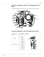
Switch Locations: AC Power Supply Circuit Board” on page 47.
Note
Switches SW1 and SW2 on the AC Power circuit board determine the AC voltage
setting for the 2920 FTT. See below for instructions on setting the AC Power level.
Note
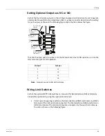
Each optional discrete output is set to NO or NC using a jumper setting. See below
for instructions on setting optional outputs as NC or NO using the appropriate jumper.
Selecting the AC Voltage Setting
Warning!
If the AC Power Selection Switches are not set properly, equipment damage
may occur.
The optional AC Power Supply circuit board can operate at one of three voltage ranges:
• Low (40 – 65 VAC)
• Medium (100-120 VAC)
• High (220 – 240 VAC).
The following figure shows the voltage selection switches.
To Set the Voltage:
1. Set SW2 to low voltage (40 - 65 VAC) or medium/high voltage (110/220 VAC).
2. If SW2 is set to 110/220 VAC, set SW1 to 110 VAC or 220 VAC as appropriate.
Caution!
If SW2 is set to 40 - 65 VAC, set SW1 to 110 VAC to avoid blowing fuse F1
(80 mA).
J8
Discrete Inputs (2)
1
Common
2
Input 3
3
Common
4
Input 4
Connector/Func-
tion
Terminal Assignment Illustration
U1
C4
J8
1
4
+
D9
C6
-
D10
40-65
SW2
VAC
+48V
S
S
110/220
110VAC
VAC
220
SW1
VAC
SW1
110 or 220 VAC
SW2
High or Low
AC Voltage
Summary of Contents for 2920
Page 2: ......
Page 16: ...2920 Float Tape Transmitter 1 Introduction 6 Installation and Operations Manual...
Page 114: ...2920 Float Tape Transmitter 6 Bi Phase Mark 104 Installation and Operations Manual...
Page 120: ...2920 Float Tape Transmitter 7 MODBUS 110 Installation and Operations Manual...
Page 126: ...2920 Float Tape Transmitter 9 L J TankWay 116 Installation and Operations Manual...
Page 158: ...2920 Float Tape Transmitter 14 Ordering Information 148 Installation and Operations Manual...
Page 193: ......


