2920 Float & Tape Transmitter
5 Display and Configuration Interface
78
Installation and Operations Manual
Analog Output User Calibration
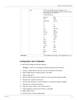
To calibrate the Analog Output, do the following:
Warning!
Obtain a hot working permit before beginning this procedure.
Output Calibration of Channel 1
1. Connect terminals A+24V and AO1+.
2. Connect a calibrated 4-20 mA Meter to terminals AO1- & AI COM.
3. If the 24VDC Output Power supply is not turned on, turn it on using the following steps:
a. Select the Basic Setup from the main Menu on the 2920.
b. Scroll to the Config Params menu.
c. Scroll to the Control parameter.
d. Set the control parameter to On.
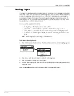
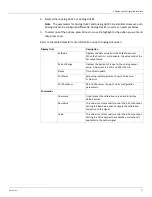
4. Select Calibration from the main Menu on the 2920.
5. Select Analog Output.
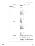
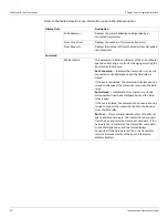
Config Params
Pnt Ref
The reference parameter used to automatically control
the 4-20 mA output signal. Some examples are Tank
Level, Tank Temperature, Encoder Level, and so on.
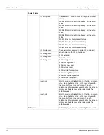
Control
When the Control Parameter is set to Enable, the data
value from the PntRef is used to control the output
value of the AO channel.
Zero
The Zero, Span, and Calibration points are similar to that
in the AI point. In this case, the AO is generating a 4-20
mA signal. If you wanted to send the 4 to 20 mA as a
level in the range of 0 to 25 feet. The zero would be 0
and the Scale would be 25. When the level was at 0 ft
the AO would send 4 mA, and when the level is at 25 ft,
the AO would send 20 mA.
Span
Cal. Point #1
Calibration points form a curve which is used to correct
the output signal, #1 corresponds to 4 mA.
Cal. Point #2
Calibration points form a curve which is used to correct
the output signal, #2 corresponds to 8 mA.
Cal. Point #3
Calibration points form a curve which is used to correct
the output signal, #3 corresponds to 12 mA.
Cal. Point #4
Calibration points form a curve which is used to correct
the output signal, #4 corresponds to 16 mA.
Cal. Point #5
Calibration points form a curve which is used to correct
the output signal, #5 corresponds to 20 mA.
All Params
Lists all Display, Commands, and Config Params in a list.
Summary of Contents for 2920
Page 2: ......
Page 16: ...2920 Float Tape Transmitter 1 Introduction 6 Installation and Operations Manual...
Page 114: ...2920 Float Tape Transmitter 6 Bi Phase Mark 104 Installation and Operations Manual...
Page 120: ...2920 Float Tape Transmitter 7 MODBUS 110 Installation and Operations Manual...
Page 126: ...2920 Float Tape Transmitter 9 L J TankWay 116 Installation and Operations Manual...
Page 158: ...2920 Float Tape Transmitter 14 Ordering Information 148 Installation and Operations Manual...
Page 193: ......


