Varec, Inc.
129
Chapter 12
Maintenance and Troubleshooting
The 2920 FTT is designed and manufactured to provide accurate and reliable operation with
no scheduled maintenance. The microprocessor is galvanically isolated from the
communications circuits. The 2920 FTT can also perform self-diagnostics. If a problem is
encountered, the transmitter isolates itself from the field communication bus.
Maintenance
Varec can provide spare parts, maintenance kits, preventive maintenance advice, training, and
warranties upon request.
Checking the CPU Status
The 2920 FTT provides a CPU status LED (D4) on the communications circuit board. The user
can visually check this LED to ensure that processor is operating properly.
Warning!
Obtain a hot permit before removing the transmitter cover with power
applied.
To Check the Processor Status:
1. Remove the 2920 FTT cover.
2. Verify that LED D4 (CPU) flashes on and off about once every second. This indicates normal
CPU operation.
Note
If LED D4 does not flash on and off about once every second, return the unit for
service.
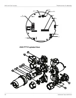
The following figure shows the
Communications Board: Diagnostic Switches and LEDs. The Bi-Phase
Mark communications board is shown as an example.
Summary of Contents for 2920
Page 2: ......
Page 16: ...2920 Float Tape Transmitter 1 Introduction 6 Installation and Operations Manual...
Page 114: ...2920 Float Tape Transmitter 6 Bi Phase Mark 104 Installation and Operations Manual...
Page 120: ...2920 Float Tape Transmitter 7 MODBUS 110 Installation and Operations Manual...
Page 126: ...2920 Float Tape Transmitter 9 L J TankWay 116 Installation and Operations Manual...
Page 158: ...2920 Float Tape Transmitter 14 Ordering Information 148 Installation and Operations Manual...
Page 193: ......


