172
Installation and Operations Manual
J
jumpers, setting for outputs
junction box
expansion
L
L&J TankWay
basic parameters
encoder type
speed mode
unit address
LED, CPU status
level calibration
calibrating
wiring
checking
Local RS-232
M
basic parameters
data format
encoder type
speed mode
temp offset mode
unit address
MNT Prothermo
MODBUS
implementation
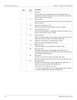
register address mappings
on non-Varec gaugehead
on Varec Gaugehead
O
configuring
contact
setting
P
parts, spare
power, input
protocols, communications
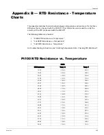
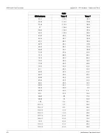
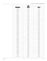
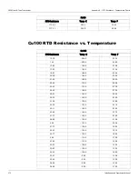
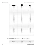
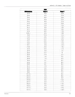
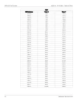
Pt100 RTD resistance-temperature chart
R
resetting the 2920 FTT
resetting the 2920 FTT, troubleshooting
resistance
line
returning to default settings
RTD
wiring
RTD data
S
installation
wiring
setting AC voltage
setting optional outputs
settings, default, returning to
software, upgrading
spare parts
SPDT switches, wiring
specifications
status, CPU
AC power board
switch specifications
calibrating
wiring
system data
system time
system wiring, terminating
T
tank data
tank level calibration
temperature data, verifying
terminating system wiring
blown fuse
overview
resetting the 2910 FTT
returning to defaults
using ViewRTU
verifying temperature data
U
upgrading
software
V
Varec gaugehead, mounting on
verifying temperature data
ViewRTU
configuring outputs with
using to troubleshoot
voltage, setting AC
W
wiring
communications protocols
limit switches
RTD
safety guidelines
terminating at transmitter
wiring diagrams
Summary of Contents for 2920
Page 2: ......
Page 16: ...2920 Float Tape Transmitter 1 Introduction 6 Installation and Operations Manual...
Page 114: ...2920 Float Tape Transmitter 6 Bi Phase Mark 104 Installation and Operations Manual...
Page 120: ...2920 Float Tape Transmitter 7 MODBUS 110 Installation and Operations Manual...
Page 126: ...2920 Float Tape Transmitter 9 L J TankWay 116 Installation and Operations Manual...
Page 158: ...2920 Float Tape Transmitter 14 Ordering Information 148 Installation and Operations Manual...
Page 193: ......

