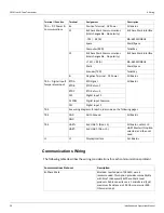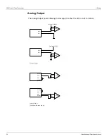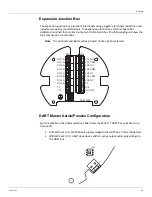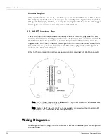
2920 Float & Tape Transmitter
3 Mounting
14
Installation and Operations Manual
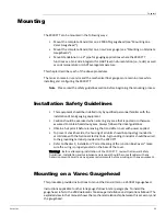
Warning! Whenever the back cover of the gaugehead is removed, stand to one side as the
last bolt is removed. If the negator motor spring is broken, the broken pieces may cause
injury when the cover is removed.
Warning! The mechanical connections between the gauge float guide cables, the float, the
tape, and the gaugehead provide an adequate ground connection for the safe drain of
electrostatic charges that may accumulate in the tank and the product. Worker activity and
worker clothing may accumulate electrostatic charges on the body of a worker. Care should
be used in flammable environments to avoid the hazard.
Make certain grounding straps are fastened properly to the case of each unit. Ground
connections via mounting clamps and bolts are not sufficient to a ensure proper ground.
1. Remove the back cover of the gaugehead (see the
2500 Automatic Tank Gauge Installation
and Operations Manua
l).
2. Remove the access cap from the back cover of the gaugehead (see the
2500 Automatic
Tank Gauge Installation and Operations Manual
). Remove and discard the four fiber wash-
ers.
3. The preferred mounting of the transmitter is to secure the transmitter onto the back cover
of the gaugehead, using the four hex head cap screws that are attached to the access cap.
Make sure that the top of the 2920 FTT housing (marked with “TOP”) lines up with the top
of the back cover. Position the circular gasket with the four bolt holes between the trans-
mitter and back cover.
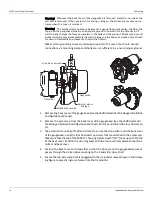
4. Position the back cover and transmitter so that the drive pin on the gaugehead sprocket
passes through the slotted drive coupling on the transmitter drive shaft.
5. Ensure the top side weep hole is plugged with the included screw as shown in the follow-
ing figure to prevent ingress of water into the transmitter.
Sprocket, wheel,
and tape
Drive pin on sprocket
Gaugehead
Slotted drive coupling
Transmitter
Summary of Contents for 2920
Page 2: ......
Page 16: ...2920 Float Tape Transmitter 1 Introduction 6 Installation and Operations Manual...
Page 114: ...2920 Float Tape Transmitter 6 Bi Phase Mark 104 Installation and Operations Manual...
Page 120: ...2920 Float Tape Transmitter 7 MODBUS 110 Installation and Operations Manual...
Page 126: ...2920 Float Tape Transmitter 9 L J TankWay 116 Installation and Operations Manual...
Page 158: ...2920 Float Tape Transmitter 14 Ordering Information 148 Installation and Operations Manual...
Page 193: ......

