Varec, Inc.
9
Chapter 2
Installation
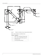
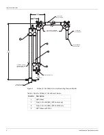
Refer to Chapter 1, Introduction to determine the feature and option codes of the unit to be
installed. Use the Table of Contents to determine the appropriate installation figure in this
Instruction Manual. These are typical installations. All situations may not be covered. Contact
Varec if additional information is needed. It is paramount that the user monitor the quality of
the installation to assure long term, accurate performance. If the quality is compromised,
inferior operation may result.
Particularly important are:
• Accurate hand gauging referenced to the tank bench mark
• Clean interior of the gauge piping
• No kinks in the tape/cable
• No noticeable binding friction in the mechanism
• Installation cleanliness
• True vertical gauge piping
• Location of float away from inlet pipes of mixers
Warning
Make certain that the tank is empty and not in service. Ensure that the tank has
been leak and pressure tested as appropriate for the liquid to be stored. Observe
appropriate safety precautions in flammable or hazardous liquid storage areas. Do not
enter a tank that has contained hydrocarbons, vapours, or toxic materials until a gas free
environment is certified. Carry breathing equipment when entering a tank where oxygen
may be displaced by carbon dioxide, nitrogen, or other gases. Wear safety glasses as
appropriate. Use a hard hat.
Warning
Under most circumstances, the mechanical connections between the guide
cables and the anchors provide a resistance to ground that is adequate for the safe
electrical drain of electrostatic charges that may accumulate in the tank and the product.
Additional grounding may be needed for products with low flash points. Worker activity
and worker clothing may accumulate electrostatic charges on the body of a worker. Care
should be used in flammable environments to avoid the hazard. Observe American
Petroleum Institute (API) Recommended Practice 2003 or other appropriate industry or
military standard.
The user provides the 1.5-inch pipe that carries the tape/cable and the necessary mounting
and support welding. The user must drill holes in the tank as needed. Assemble the necessary
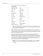
tools and equipment at the work site. Table 6 on page 10 lists typical tools and equipment that
may be needed. Use a drop cloth to maintain tool, equipment, and installation kit cleanliness.
Plan the pipe routing. Locate the roof connection into the tank interior within arms reach of a
manhole or an inspection hatch.
Summary of Contents for 6700
Page 2: ......
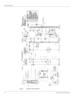
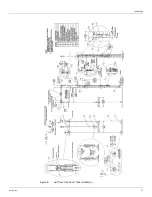
Page 25: ...Installation Varec Inc 17 Figure 8 Half Travel Cone Roof Tank Installation 16 50 419...
Page 39: ...Installation Varec Inc 31 Figure 15 Bolted Tank Installation 16 50 419...
Page 51: ...Installation Varec Inc 43 Figure 20 Severe Service Cone Roof Tank Installation 12 50 318...
Page 70: ...Liquid Level Indicator 62 Installation and Operations Manual...
Page 73: ......

