Liquid Level Indicator
20
Installation and Operations Manual
30. Check the indicator tape/cable path between the float and the gaugeboard to be sure that
the tape/cable is not kinked or twisted. Also check the float guide cables for kinks.
31. Make certain that the float guide cables are parallel.
Note
If auxiliary equipment is to be installed, do it prior to crimping the cable connector.
The accessory drive elbow should not be used for half-travel level indication. The use of
auxiliary units not manufactured or supplied by Varec will void any Varec warranty and will
relieve Varec of any obligation to service the product under warranty.
32. Install indicator.
Full Travel Gaugeboard:
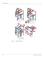
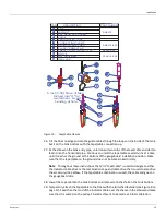
Slip the indicator over the gaugeboard. Put the cable crimp on the end of the cable, then
thread the cable through the hole in the indicator. Loop the cable on the outside back
through the cable crimp and temporarily tape it to the crimp (see Figure 7 on page 16).
Half Travel Gaugeboard:
Remove one side channel from the indicator. Position indicator on the gaugehead and
reassemble the side channel. Thread the cable through the pulley on the indicator. Put
the cable crimp on the end of the cable. Thread the cable through the hole in the
gaugeboard connector plate. Loop the cable on back through the cable crimp and
temporarily tape it to the crimp (see Figure 8 on page 17).
33. Tape the gaugeboard indicator to the gaugeboard at 2.00 inches [50.8 mm] to hold it in
place. Adjust the cable tension until the float barely lifts off the tank floor, then crimp the
cable connector and remove the tape.
Note
As the float is four inches [101.6 mm] high and its waterline is at its equator, it can
-
not register the last two inches [50.8 mm] of liquid in the tank.
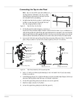
34. Tie a line longer than the height of the tank to the indicator.
Caution
Do not allow the float to fall back to the floor of the tank. Damage may result.
35. Slowly pull down on the indicator and lift the float to the top of the tank. Travel should not
produce noticeable binding. Slowly lower the float to the floor of the tank.
36. Remove the pull line.
Summary of Contents for 6700
Page 2: ......
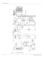
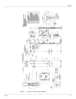
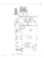
Page 25: ...Installation Varec Inc 17 Figure 8 Half Travel Cone Roof Tank Installation 16 50 419...
Page 39: ...Installation Varec Inc 31 Figure 15 Bolted Tank Installation 16 50 419...
Page 51: ...Installation Varec Inc 43 Figure 20 Severe Service Cone Roof Tank Installation 12 50 318...
Page 70: ...Liquid Level Indicator 62 Installation and Operations Manual...
Page 73: ......

