Liquid Level Indicator
12
Installation and Operations Manual
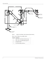
Installation of Oil Seal, 8.5-Inch Water Column Operating Pres
-
sure Model
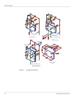
Refer to Figure 2 on page 4.
1. Apply appropriate pipe thread compound and install long pipe (1) into 135-degree elbow
with bottom drain (4).
2. Apply pipe thread compound and install short pipe (2) into 135-degree elbow with bottom
drain (4).
3. Apply pipe thread compound and install 135-degree elbow (3) onto long pipe (1).
4. Apply pipe thread compound and install 90-degree elbow supplied with gauge kit onto
short pipe (2).
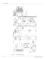
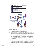
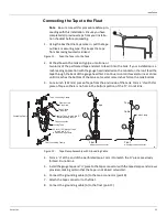
5. Adjust the assembly to provide the tape/cable path illustrated in Figure 2-8 on page 29.
6. Provide 1.5-inch pipe installation, as required.
7. Proceed with the remainder of the tank installation to the paragraph Initial Lubrication,
then fill the oil seal as follows:
a. See Chapter 4, Maintenance, for oil selection.
b. Remove the cover from 90-degree elbow.
c. Fill to halfway in the short pipe.
Note
To drain the oil, open the plug in 135 degree elbow (4).
Summary of Contents for 6700
Page 2: ......
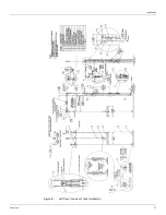
Page 25: ...Installation Varec Inc 17 Figure 8 Half Travel Cone Roof Tank Installation 16 50 419...
Page 39: ...Installation Varec Inc 31 Figure 15 Bolted Tank Installation 16 50 419...
Page 51: ...Installation Varec Inc 43 Figure 20 Severe Service Cone Roof Tank Installation 12 50 318...
Page 70: ...Liquid Level Indicator 62 Installation and Operations Manual...
Page 73: ......

