Wiring
18
Installation and Operations Manual
4.2
8410 WFT Connectors, Switches, and Low Voltage Wiring Diagram (DC Version)
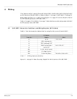
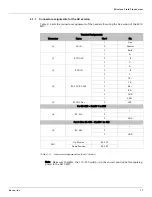
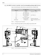
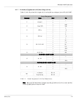
Table 4-3 lists the connectors and switches for wiring the DC version of the 8410 WFT.
Figure 4-2 shows the wiring diagram for the low voltage version of the 8410 WFT.
Figure 4-2: 8410 WFT Wiring — Low Voltage Version
Low Voltage Version
Connector
Purpose
Notes
J1
Voltage In
30-65 VAC / 6-90 VDC
J5
RTD Feedthrough IN
J6
RTD Feedthrough OUT
J8
Serial Communications
RS-232/RS-485
J9
24VDC OUT
SW1
RS-232/RS-485 Switch
SW3
Radio Setup Button
Puts radio in setup mode
SW6 and SW7
Voltage Selector
Selects AC/DC and high/low DC
voltage.
Table 4-3:
DC Wiring Connectors and Switches
SW1 - RS232/RS485 Switch
SW6 - AC/DC
Selector Switch
Antenna Connector
Radio Programming
Header
DC Voltage
Selector Switch
SW7 - High / Low
J8 - RS232/RS485 In
J2 - Surge Ground
J9 - 24VDC Out
J5 - RTD In
J6 - RTD Out
J1 - Voltage In
SW3 - Radio Setup
Mode Button
AC DC HV LV
Summary of Contents for RS-232
Page 2: ......
Page 20: ...Preparing for Installation 12 Installation and Operations Manual...
Page 22: ...Mounting 14 Installation and Operations Manual...
Page 28: ...Wiring 20 Installation and Operations Manual...
Page 30: ...Setting Up the Transceiver Using Tool Suite 22 Installation and Operations Manual...
Page 34: ...LED Operations 26 Installation and Operations Manual...
Page 40: ...Ordering Information 34 Installation and Operations Manual...
Page 41: ......

