CB-800
CB-1000
2.4.3 M
ACHINE
C
ONTROL
E
LEMENTS
2.4.3.1 H
ANDLEBAR
ADJUSTMENT
A
HEIGHT ADJUSTMENT
:
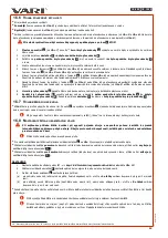
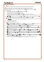
Only adjust the handlebar positions when the machine is stationary, and its engine is switched off. There is the
risk of losing control of your machine!
•
Loosen and completely unscrew the plastic wing screw
1
, remove the flat washer
2
.
•
Pull out the bolt to the left
3
from the handlebar handles
4
.
•
Adjust the height of the handlebars above the ground so that the handlebars are comfortable to hold. You can choose from a total of 6
positions - three holes
A
in the handlebar handles
4
and two holes
B
in the tubular handlebar holder
5
.
•
Insert the bolt
3
from the left into both ends of the handlebar handles
4
, place the flat washer on the bolt
2
, screw in the plastic wing
bolt
1
and tighten it securely.
B
PARKING AND TRANSPORT HANDLEBAR POSITION:
•
Loosen and unscrew the plastic wing screw
1
byabout 1 cm.
•
Flip the handlebars towards the engine, the right handlebar should have a small gap from the engine oil dipstick.
•
Carefully tighten the plastic wing bolt
1
.
2.4.3.2 L
EVER
FOR
THE
BRUSH
LOWERING
PULLEY
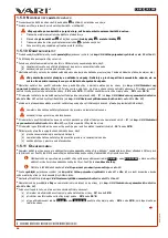
To switch the brush drive on and off, use lever
1
(in
Fig. 3
), located on the right handle.
The lever must be always entirely pressed towards the handle, otherwise the clutch slip may occur.
It is forbidden to remove accumulated snow that prevents the drive from starting smoothly by starting the
brushes via controlled belt slip. First, clear the brush area, and only then continue in your work.
Release the control lever as quickly as possible whenever the drive starts slipping.
The brush start may be accompanied with partial slipping of the V-belt and associated side phenomena (rattling, whistling).
When the belt has been run in, these effects usually disappear.
Do not hold or slow down the lever during its movement back to the default position. Always release the lever
quickly.
•
For the procedure for starting and stopping the brush drive, see
on
page 29.
2.4.3.3 W
HEEL
DRIVE
PULLEY
LEVER
•
To switch the machine’s travel on and off, use lever
2
(in
Fig. 3
), located
on the left handlebar.
The lever must be always entirely pressed towards the handle, otherwise the clutch slip may occur.
Do not adjust the speed of the machine, e.g., by partially depressing the travel lever - this causes increased wear
on the belt.
When the machine's travel is switched off, the machine may reverse sharply due to the counter-rotation of its
brushes. Therefore, always keep a sufficient clear space behind you, free of obstacles.
•
For the procedure for lowering the brushes, see
Chap.2.5.5 Machine travel
on
page 29.
2.4.3.4 A
DJUSTING
THE
ANGLE
OF
THE
BRUSHES
•
To adjust the brushes sideways, use the long lever
3
(in
Fig. 3
), located in the machine's axis.
Always switch off the brush drive and the machine travel before changing the sideways brush setting.
•
For the procedure for adjusting the brushes sideways, see
Chap.2.5.9 Rotating the sweeping rollers axis
on
page 31.
2.4.3.5 A
DJUSTING
THE
BRUSH
PRESSURE
•
To adjust the brush pressure, use the plastic control knob
4
(in
Fig. 3
) protruding from the front plastic cover.
•
When you have finished working with the machine (e.g. when parking or storing the machine), always extend the support wheel so that
the brush bristles do not touch the mat and are about 1-2 cm away from it. This prevents deformation of the bristle ends.
•
For the procedure for adjusting the brush pressure, see
Chap.2.5.8 Setting the pressure of the sweeping rollers
on
page 30.
2.4.3.6 A
CCELERATOR
LEVER
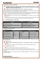
The main positions of the lever are locked in place by a simple push-pull system in the lever body. The accelerator lever positions
(
1
=
STOP
,
2
=
MIN
,
3
=
MAX
and
4
=
CHOKE
) are described in
Fig. 7
.
27
re
vi
ze
1
2/
20
21

