F-530.1
21
6.4 V-belt replacement and adjustment of tension pulley
The V-belt should be replaced according to its wear (cracked sides, torn belt, sides worn
out down to belt carrier fibres, belt pulled out of shape) or after about 200 hours of operation
at the maximum. In this machine, the belt stretched to maximum is considered a belt in which
the distance between the internal belt surfaces is lesser than 7 mm (with the pressed lever of
mowing knife drive clutch). The replacement procedure is as follows:
a) Drain petrol from the engine tank. Dismount the accelerator lever (2x spanner No. 8)
from the handlebars. Bowden cable should never be dismounted from the control on the
engine!
b) Unscrew three safety nuts (spanner No. 13) on the engine flange and pull the engine out
from the machine frame upwards. Never use force to pull the engine from the frame!
Never put the engine on the side. Oil might get into the exhaust or into the air
cleaner. The best engine seating is with the lower flange dwelling on two lintels
which are at least 7 cm high.
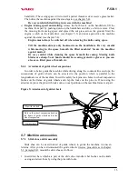
c) Dismount the V-belt casing (spanner No. 8, spanner No. 10). Dismount the bolt with nut
in front of the driven belt pulley (see Fig. 8.3) (spanner No. 10). Remove the old V-belt
and replace it with a new one.V-belt marking is GATES A45 BareBack.. It is also
possible to use an equivalent V-belt made by other manufacturers at a size of A13x1150
Li (Li=internal length). However, the belt must be made without rubber on belt sides!
Only this belt model will guarantee that there will be no belt extension and that the knife
drive start will be continuous at engaging the clutch.
Should a different belt model be used, the machine manufacturer does not bear any
liability for the correct and full functioning of the gear!
d) Put the engine back in place. Pins on the belt pulley must fall into holes in the driven part
of the coupling mounted on the gearbox. Bolt the engine with three safety nuts with flat
washers and screw the accelerator lever back onto the handlebars.
e) Install the V-belt into the groove in the belt pulley on the engine.
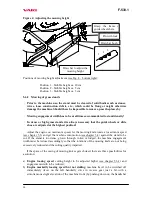
f) Check the operation of the tightening pulley and adjustment of guide lamination. With
the lever on the right handlebar grip being completely pressed down, the pulley must
ensure a sufficient belt tension (spring on the cable being extended by about 10 mm as
compared with the normal loose condition). Possible corrections are to be made by means
of the adjustment bolt No. 1 (see Fig. 12). With the lever switched off, the pulley must be
inclined away from the longitudinal machine axis by 0 - 5° (at maximum) = with the belt
convex side being approx. 1.5 – 2.0 cm from the bottom of the tightening pulley (see Fig.
11) and the cable in the Bowden of the tension pulley must exhibit no slackness. In the
case that the adjustment bolt is completely screwed out and it is necessary to tighten the
V-belt, the spring on the cable can be hooked into the front hole on the arm of the
tightening pulley (see Fig. 11 bottom, note: this connection can be used already from the
manufacturer) and the belt tension can be adjusted once again. Guide lamination on the
right side of the machine must be parallel to the belt and at a maximum distance of 1 – 2
mm from the belt convex side.
g) Mount the bolt back in front of the driven belt pulley and plastic casing of the belt.
If the gearbox is dismounted from the machine frame, it is necessary to ensure axial
alignment of gearbox shafts and engine at the reverse assembly. This operation
should therefore be entrusted to an authorized service shop which has to have
available an original and manufacturer-approved centring fixture.
Summary of Contents for F-530.1
Page 1: ...Mulcher F 530 1 Instructions for use 2003...
Page 27: ...F 530 1 27 9 1 Knife casing and guide wheels...
Page 29: ...F 530 1 29 9 2 Mowing knife drive...
Page 31: ...F 530 1 31 9 3 Handlebars...
Page 33: ...F 530 1 33 9 4 Wheel drive gear...
Page 35: ...F 530 1 35 9 5 Gearbox...
Page 37: ...F 530 1 37 9 6 Swinging and mixing knives slide shoe...
Page 41: ...F 530 1 41 Text and illustrations c 2002 VARI a s Publication No VL 061 2002...

