F-530.1
9
On the upper part of the frame there is a 4-stroke combustion engine to prime the machine
travel gear through the pin clutch and through the V-belt the mowing knife which is installed
on the knife shaft through the friction clutch. The knife is made of high-quality hardened
steel. The mowing knife drive is to be switched on by the pulley-controlled lever on the
handlebars. A part of the mowing knife is also a safety brake to stop the mowing knives after
the mowing knife drive clutch lever has been released.
The knife with bent ends and blade is installed on the knife shaft through the friction
clutch.
On the tube handlebars whose height can be adjusted in three positions there is a control
lever of the travel gear, a control lever of mowing knife drive gear with brake, and an
accelerator lever to set-up engine speed.
Machine accessories include a slide shoe made of steel tube and a set of swinging and
mixing knives.
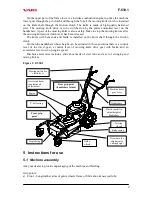
Figure 1: F-530.1
5 Instructions for use
5.1 Machine assembly
Ask your dealer to provide unpackaging of the machine and briefing.
Grip points:
a) Front: - Longitudinal arms of guide wheels frame or Slide shoe transversal tube;
Guide
wheels
Front casing
Draw bars for
adjustment of
cutting height
Driving
wheels
Engine
Handlebars
Knife casing
Mowing knife drive
clutch lever
Acceleratorlever
(enginespeed
adjustment)
Machine travel
gear lever
Plastic rosebit to
adjust height of
handlebars
V-belt casing
Front grip
point
Rear grip point
(handlebars folded)
Summary of Contents for F-530.1
Page 1: ...Mulcher F 530 1 Instructions for use 2003...
Page 27: ...F 530 1 27 9 1 Knife casing and guide wheels...
Page 29: ...F 530 1 29 9 2 Mowing knife drive...
Page 31: ...F 530 1 31 9 3 Handlebars...
Page 33: ...F 530 1 33 9 4 Wheel drive gear...
Page 35: ...F 530 1 35 9 5 Gearbox...
Page 37: ...F 530 1 37 9 6 Swinging and mixing knives slide shoe...
Page 41: ...F 530 1 41 Text and illustrations c 2002 VARI a s Publication No VL 061 2002...


