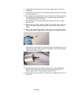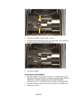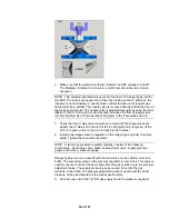
4. Remove the external tip and replace it with the Internal measuring tool
provided with the system. If you do not have an Internal measuring tool, you
will need a ruler to measure the column length.
5. Using a sapphire-, or carbide-tipped scribing tool or ceramic scoring wafer,
score the column once lightly at the end of the measuring tip and cleanly
break the column. If there is no measuring tip available, cut the end of the
column 8 mm beyond the internal transfer line tip opening after the internal
tip is installed.
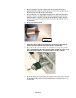
6. Remove the measuring tool.
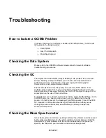
Internal Tip
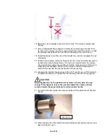
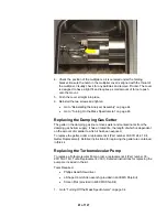
7. Screw the brown Polyimide internal tip onto the transfer line and clean the
column and surrounding area with methanol and a lint-free wipe.
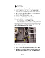
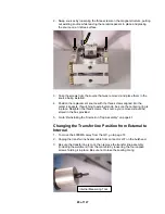
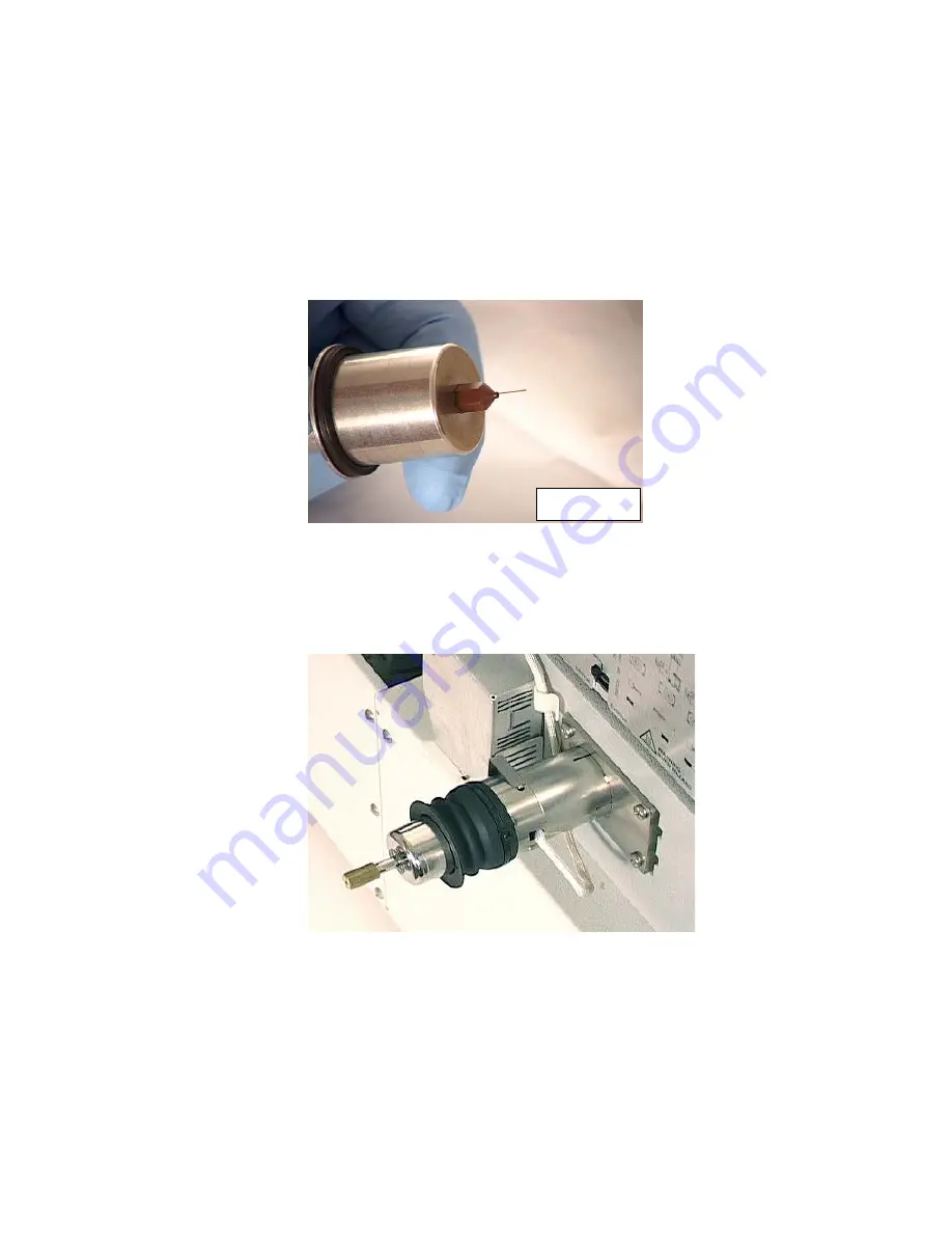
8. Return the transfer line assembly to the manifold, positioning it towards the
rear of the instrument, and tighten the four screws. Be sure that the O-ring is
clean and properly seated in the manifold groove (no kinks or twists).
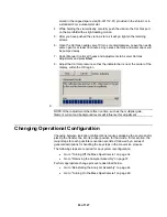
9. Route the transfer line heater cable through the white retainer clip on the side
of the manifold and under the thermocouple gauge. Then plug it into J37 on
the bulkhead.
86 of 127
Summary of Contents for 4000 GC
Page 4: ......
Page 40: ...6 of 127...
Page 77: ...3 Check source connection pins for proper alignment and straighten as necessary 43 of 127...
Page 124: ...90 of 127...
Page 148: ...114 of 127...


