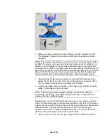
2. Make sure that the electron multiplier, filament, and RF voltage are all off.
The Multiplier, Filament (Ion Source), and RF text should be red or black -
not green.
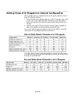
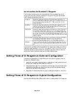
NOTE: Two solenoid-operated valves control the flow of CI reagent gas into the
manifold. The valves are opened and closed by clicking on the CI button on the
Instrument Control display. A needle valve controls the amount of reagent gas
flowing into the manifold. The needle valve is mounted directly behind the door of
the mass spectrometer. The needle valve is adjusted manually by using the knob
labeled CI GAS. Turning the knob clockwise increases the flow of reagent gas
into the manifold. See Functional Block Diagrams in the Pneumatics section.
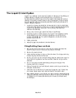
3. Check that the CI Gas solenoid valves are closed. When these valves are
closed, the CI Gas icon to the left of the ion trap symbol is not green. (If the
CI icon is green, click on the icon so that it turns to black.)
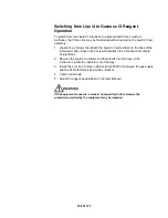
4. Install a two-stage pressure regulator on the reagent gas cylinder or lecture
bottle. Tighten the connection securely.
NOTE: A two-stage pressure regulator typically consists of the following
components: Secondary valve, pressure adjustment valve, supply pressure
gauge, and delivery pressure gauge
Reagent gas is turned on and off with the main valve on the cylinder or lecture
bottle. The secondary valve on the pressure regulator is next in line. This valve is
used for coarse control of the flow of gas from the gas cylinder up to the pressure
adjustment valve. The supply pressure gauge is used to monitor the gas
pressure in the bottle. The pressure adjustment valve is used to set the head
pressure of the gas delivered to the mass spectrometer.
5. Connect one end of the 1/8" OD gas supply line to the pressure regulator.
94 of 127
Summary of Contents for 4000 GC
Page 4: ......
Page 40: ...6 of 127...
Page 77: ...3 Check source connection pins for proper alignment and straighten as necessary 43 of 127...
Page 124: ...90 of 127...
Page 148: ...114 of 127...

