Transfer Line
A stainless steel tube transfer line directly couples the GC to the mass
spectrometer. The purpose of the transfer line is to keep the GC column warm as
the column enters the mass spectrometer to avoid condensation of the sample,
which could result in tailing. One end of the transfer line enters a hole in the right
side of the GC before passing into the GC oven. The other end enters the
vacuum manifold in one of two positions, depending on where the sample is to
be ionized. If the sample is to be ionized in the external source, the transfer line
is inserted into the source volume. If the sample is to be ionized in the trap, the
transfer line is inserted into a hole in the trap close to an electron generating
filament. Two different tips must be used to extend the GC column into the point
of ionization, depending on the mode used. A short Polyimide tip is used for
internal ionization and a long metal tip is used for external ionization. The body of
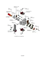
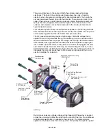
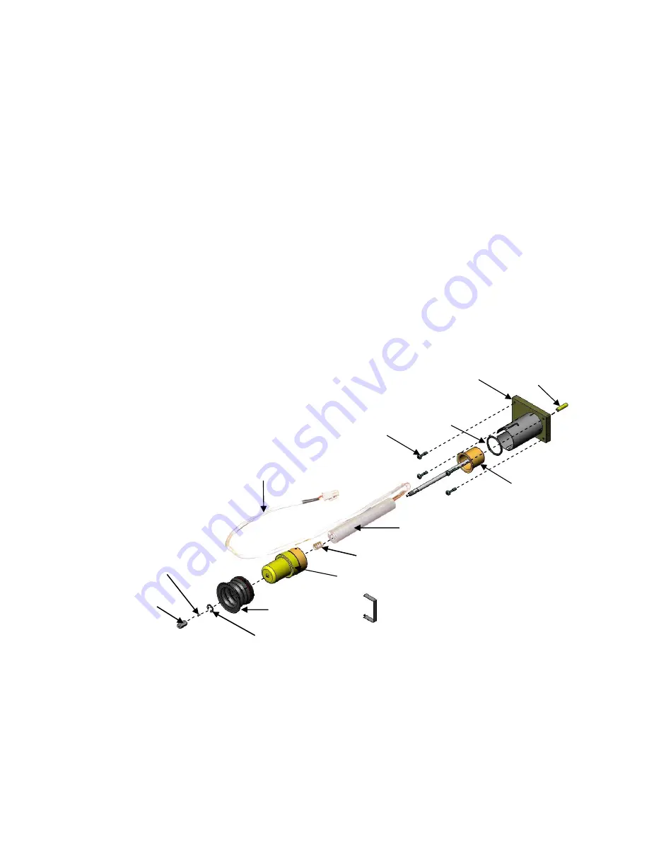
the transfer line consists of a stainless steel body fitted with a center tube, a heat
exchanger, and a boot. The heat exchanger is an aluminum cylinder that
contains a cartridge heater and a thermocouple as the temperature sensor. The
temperature sensor measures the temperature of the tube. The cartridge heater
heats the cylinder, which distributes heat evenly throughout the length of the
transfer line tube. The boot of the transfer line, which mates to the GC, prevents
hot air from leaking from the GC oven.
Bayonet Mount
Feature
Block Heater
Weldment
Compression Spring
Retaining
Clip
Quad
O-Ring
Brass Nut
Air Seal Boot
Nose-Collar
Captive Screw
(4 places)
Heater Cable
No-Hole Ferrule
Weldment
Retaining Clamp
(E Clip)
Exploded View of Transfer Line
A bayonet mount feature secures the transfer line. Before you remove the trap,
push gently on the bayonet mount as you twist it counterclockwise and pull the
mount out. Make sure the transfer line extends out from the trap.
9 of 127
Summary of Contents for 4000 GC
Page 4: ......
Page 40: ...6 of 127...
Page 77: ...3 Check source connection pins for proper alignment and straighten as necessary 43 of 127...
Page 124: ...90 of 127...
Page 148: ...114 of 127...

