Reinstalling the Source/Ion Trap Assembly
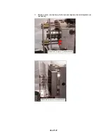
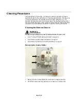
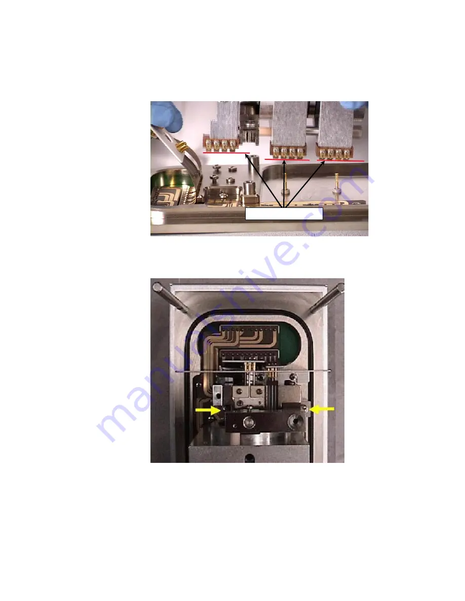
Check to see that all the connection fingers are even as shown. If any fingers are
substantially bent, bend them back in line with the other fingers.
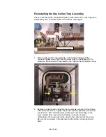
Connector Fingers Down
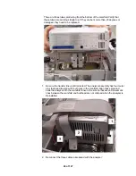
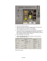
1. Place the Source/Ion Trap assembly on the analyzer flange with the
connector fingers down. Align the two screw holes on the flange with the
screws on the Source/Ion Trap assembly then tighten the two screws evenly.
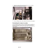
2. Replace the heat shield and tighten the two screws securing it to the flange.
If the external source is in place, the shield should be positioned on the rear
set of screws.
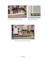
The shield should be positioned on top of the ridge on the
source heater block, see figure that follows. If using the internal
configuration, the screws should be closer to the center part of the source.
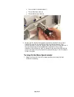
Be sure the two screws in the alternate shield position are also tightened
down.
41 of 127
Summary of Contents for 4000 GC
Page 4: ......
Page 40: ...6 of 127...
Page 77: ...3 Check source connection pins for proper alignment and straighten as necessary 43 of 127...
Page 124: ...90 of 127...
Page 148: ...114 of 127...

