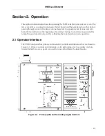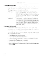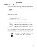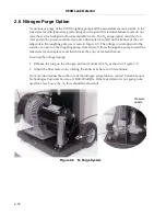
2-15
959D Leak Detector
6. Close the valve in the tuning leak.
7. Press
START
.
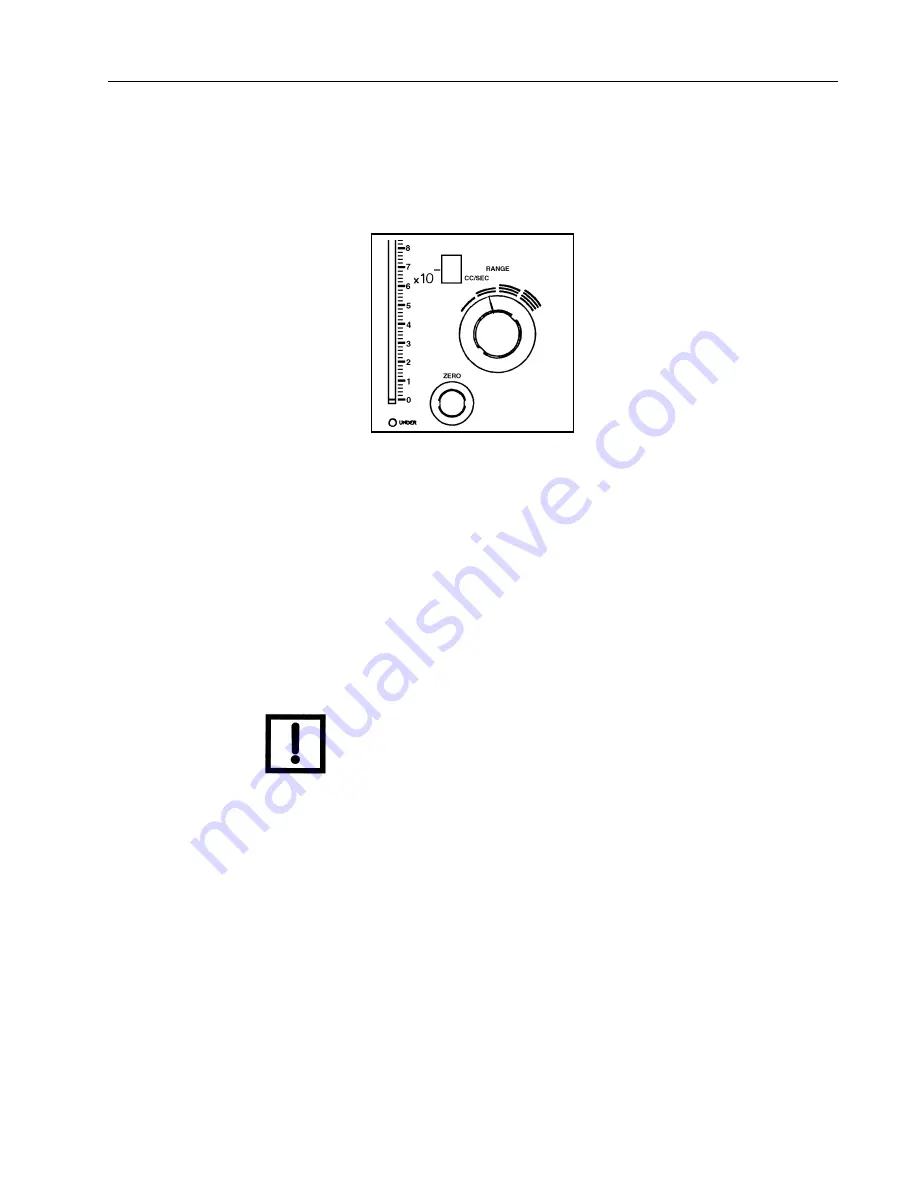
8. Once the leak rate displayed on the bar graph has settled, set
RANGE
in the
two-arcs
(10
-6
) position.
Figure 2-8
Range at Two Arcs
9. Slowly adjust
ZERO
on the primary panel.
If zeroing cannot be achieved, adjust
COARSE ZERO
on the secondary panel, and then
ZERO
.
10.
Very slowly
open the tuning leak valve until the test port pressure rises to 100 mTorr.
Note a corresponding rise in the leak rate indication.
11. If the bar graph does not display between 1 and 9, move
RANGE
until it does.
12. Slowly adjust
FOCUS
and then
ION
for a maximum on the leak rate display.
NOTE
The ION control is a 10-turn potentiometer and normally needs
to be adjusted only slightly for a maximum peak on the display.
When tuned to helium, the outer dial on the ION control at the
12 o'clock position should indicate between 2 and 8.
A change in one adjustment may affect the others. Therefore, it may be necessary to
repeat step 9 through step 12 until no significant change occurs in the leak rate reading.
The 959D is now tuned to helium. When performed correctly, day-to-day changes are
very small, and daily adjustment may not be required.
13. Close the tuning leak valve and verify that the leak rate drops to zero.
If the leak rate does not drop to zero, repeat this procedure to retune the spectrometer
tube beginning with step 9.
14. Press
VENT
and remove the tuning leak.
Proceed with testing.
Summary of Contents for 959D
Page 16: ...959D Leak Detector 1 2 D R A F T 9 1 3 0 2 Figure 1 1 Model 959D Leak Detector ...
Page 28: ...959D Leak Detector This page intentionally left blank D R A F T 9 1 3 0 2 ...
Page 48: ...959D Leak Detector This page intentionally left blank D R A F T 9 1 3 0 2 ...
Page 68: ...959D Leak Detector This page intentionally left blank D R A F T 9 1 3 0 2 ...
Page 78: ...959D Leak Detector This page intentionally left blank D R A F T 9 1 3 0 2 ...
Page 81: ......

