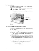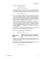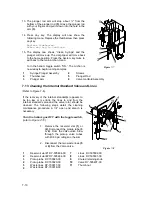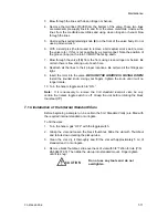
7-4
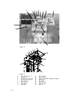
4. Attach the flangeless fitting and ferrule (11) into the hole in the center of the
valve manifold (14). Be certain the line, with ferrule, is seated all the way to
the bottom of the hole. Finger-tighten the nut.
7.3
Cleaning the Soil Transfer Line Frit (PN DY-505599-00)
(Refer to Figure 7-2 and Figure 7-3)
Removal
1. Remove the soil probe as described in Section 7.1.
2. Blow into the left side with about 40-50 psi of clean air or nitrogen.
Installation
1. Install the probe as described in Section 7.1.
2. Be certain all fittings are tight.
7.4
Replacement of the Water Line Screen (P/N DY-505598-00).
(See Figure 7-2 and Figure 7-3).
1. Remove the flangeless fitting and ferrule (11) from the valve manifold (14).
2. Using a small diameter pick or pointed wire, reach into the hole and pull the
screen out.
3. Insert the screen into the hole, the white side of the screen faces out.
4. Insert the flangeless fitting and ferrule (11) into the hole in the manifold (14).
Finger-tighten the nut.
7.5
Replacement of the Soil Transfer Line
(Nickel Line Only) (DY-505745-00)
(See Figure 7-2 and Figure 7-3).
Removal
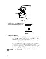
1. Remove the upper soil valve cover shown in Figure 7-1. Referring to Figure
7-2 and Figure 7-3, loosen and remove the nut (4) securing the transfer line
to the upper soil valve (15).
2. If necessary, remove any covers from the purge and trap, allowing access to
the fitting on the end of the transfer line. Disconnect the line from the purge
and trap.
3. Cut one end off, with fitting, from the line.
4. Slide the line out of the heater's sheath.
Replacement
1. Uncoil and straighten the new line. Insert the line into the heater's sheath.
Carefully slide the line all the way through until it is inside the cabinet. Blow
through the line with helium before connecting.

