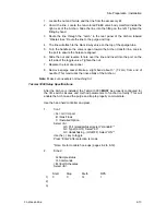
1-4
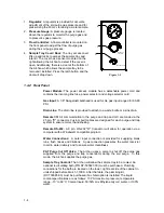
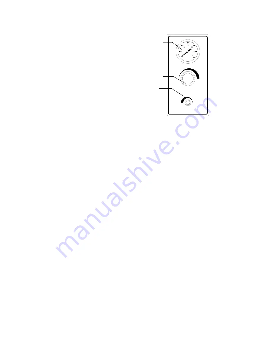
1. Regulator: A regulator is provided for accurate
adjustment of the soil purge gas pressure and for
pressurizing the 40 mL vial during a water sample.
2. Pressure Gauge: A pressure gauge is located
above the regulator to monitor the purge gas and
to pressurize gas pressure.
3. Flow Controller: A flow controller is mounted on
the front panel to adjust the flow of purge gas
during the soil purge process.
4. Sample Tray Cover/ Door: The tray access cover
lifts up and locks to access the sample tray and
interior. The cover has a sensor mounted on the
right allowing the Archon to detect if the cover is
open. Additionally, there is a door at the bottom of
the Archon which allows the sample tray to be
removed / installed. Press the latch button and the
door will drop down.
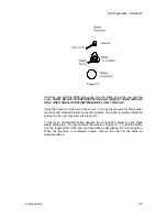
P U R G E G A S
P R E S S U R E
P U R G E G A S FLO W
+
_
+
Figure 1-2
1.4.2 Rear
Panel
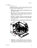
Power Module: The power access module has a detachable power cord and
contains the incoming line fuse, power selector and voltage selector card.
Gas Input: A 1/8" Swagelok® bulkhead is used for He gas input ranged for 60-90
PSI.
Drain Line: The drain line is provided to attach to a waste bottle or a sink drain.
Remote I/O: All communication to the purge and trap and GC are made via the
25 pin, "D" connector. Custom built cables are designed for each purge and trap
system to ensure correct handshaking.
Remote RS-232: A 9 pin, RS-232 "D" Connector will allow for operation via a
computer with a Windows® compatible program.
Water Connections: A water input connection is provided for supplying blank
runs, flush rinses and dilutions. A gas connection pressures the water reservior
to aid in water delivery and to ensure water cleanliness.
PAT Purge Cut Off Valve: The Archon uses a valve to shut off the purge gas
supplied from the purge and trap concentrator during the soil purge. In this
mode, the Archon supplies the purge gas.
Sample Tray Coolant: The Archon will allow the sample tray to be cooled. An
optional recirculating bath (P/N DY-505627-00) must be purchased. Plumbing
connections for the bath are located on the lower, right rear side of the cabinet in
units shipped before March 1,1999. After that date, the plumbing kit
(DY-700085-90) must be purchased if a chiller option is installed. The liquid
coolant specifications are as follows: 10 PSI maximum pressure; temperature
range, -10
to 60
C; Coolant liquid, 50/50% mix Ethylene Glycol / water, or 100%
water.
2
1
3


