I
NSTALLATION
Column Installation and Conditioning
CP-3800 GC Getting Started Manual
33
Varian Test
Column
At points throughout this manual, specific values and conditions are given
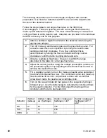
for the analysis of Varian Test Samples on Varian Test Columns. The
following table provides information on Varian Test Columns.
Varian Test Columns
Column Description
For use with
Injector Models
Part
Number
Packed 50 cm x 1/8
″
OD stainless steel
OV-101.
1041/1061
Packed Adapters
03-912300-30
Capillary 4m x 320
µ
ID DB-1 fused silica.
1079
03-912805-99
Capillary 4m x 320
µ
ID DB-1 fused silica (a)
connected to a short pre-column of 0.53 mm
fused silica (b) using a Press-Fit
connector
(c). The above parts are also available as a
kit (d).
1041/1061
03-912805-99 (a)
00-997564-03 (b)
00-997668-03 (c)
03-912809-90 (d)
Identify
Carrier Gas
Controls and
Turn on Flow
Gases are plumbed at the factory through the rear bulkhead fittings into the
inlet manifold, then to the pneumatic controls in the pneumatics
compartment. The pneumatic controls can be either electronically controlled
(EFC) or manually controlled and are different for each injector system.
If your injector
model is a ...
Carrier gas flow is regulated by a ...
1041/1061
Type 3 EFC or upgrade to type 4 with valving.
1079
Type 1 EFC or Flow controller (controls flow into
injector) and a Back pressure regulator (controls flow
through column)
•
Carrier gas flow is adjusted at the user interface for EFC or at the
pneumatics panel for manual pneumatics. For manual pneumatics
carrier gas systems, identify the controls for carrier gas flow at the
pneumatics panel for your injector system. These pneumatic controls
are identified by their location, i.e., front, middle, rear.
•
Turn on carrier gas flow by adjusting the manual flow controller or
setting a positive pressure or flow on the EFC system.
•
Verify that there is a positive pressure on the pneumatics panel pressure
gauge or EFC status screen.


