CP-3800 GC Operator’s Manual
113
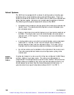
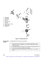
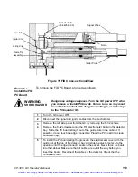
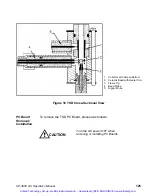
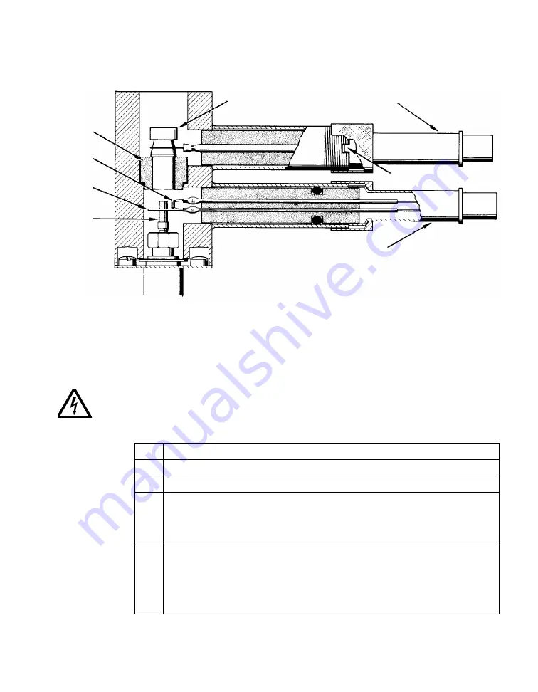
Figure 15 FID Cross-sectional View
Remove /
Install the FID
PC Board
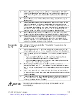
To remove the FID PC Board, proceed as follows:
WARNING:
SHOCK HAZARD
Dangerous voltages exposed. Turn the GC power OFF when
you remove or install PC boards. Failure to do so may result
in accidental contact with dangerous voltages, or in damage
to the PC board or GC.
1
Turn the GC power OFF.
2
Disconnect the signal and ignitor cables from the electrometer.
3
Remove the left side panel from the GC by removing the 8- 32 screws.
4
Remove the 8-32 screw securing the FID electrometer board in the detector
bay. Slide the PC board straight out of the guide slots in the cabinet. If
possible, do not touch the edge connectors. Place the PC board in a clean
anti-static bag.
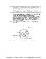
5
To install the PC board, align the groove in the electrometer cover with the
guide rail at the top of the detector bay and slide the electrometer into the
opening until the edge connector seats in the socket. Never force the board
into the cabinet. Make sure that all cables are out of the way before you
insert the board. Reconnect the cables to the detector. Check that the
connectors mate.
Collector Tube
(03-949587-00)
Signal Probe
Notch
Ignitor Probe
Insulator
Ignitor Coil
Spring Clip
Flame Tip
Assembly
Artisan Technology Group - Quality Instrumentation ... Guaranteed | (888) 88-SOURCE | www.artisantg.com

