CP-3800 GC Operator’s Manual
161
ACTIVE
METHOD
EDIT
METHOD
CTRL
RUN
TIME
END
TIME
Method 1
Method 1
0.00
20.00
Detectors: Front: TCD Middle: FID Rear: None
ANALOG OUTPUT A
Time
Signal Source
Attenuation
Initial
Front Detector
1
10.00
Middle Detector
1
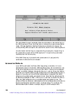
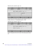
The screen shown is used to time program the signal source of the analog
output. By default analog output A is assigned to the front detector. In the
example above, the 3800 is configured with a TCD in the front detector
position and an FID in the middle detector position. The analog port is
programmed to transmit the TCD signal for the first 10 minutes of the run and
then switch to the FID for the remainder of the run. This mode of operation is
known as detector switching.
Note that the attenuation should normally be set to 1. Most of the devices to
which the analog output will be connected, such as integrators and analog
data systems, are equipped with attenuation control. The signal sent from
the GC in this case should not be attenuated.
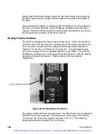
The 3800 has a number of analog cable options, depending on the device to
which the cable is connected. All cables have a 15 pin D-shell connector on
one end to attach to J6 on the 3800 and have the appropriate connectors on
the other end of the cable for the devices to which they are being attached.
The following cables are available:
•
Two channel cable for Varian ADC Board: 03-925672-01. This cable is
equipped with two 9 pin D-shell connectors for the ADC Board. The
Varian ADC Board can collect a maximum of two channels of analog
data. Analog Output Port A is connected to the Varian ADC Board
Channel A. Similarly, Analog Output Port B is connected to the Varian
ADC Board Channel B. Analog Output Port C is not connected.
Artisan Technology Group - Quality Instrumentation ... Guaranteed | (888) 88-SOURCE | www.artisantg.com

