CP-3800 GC Operator’s Manual
9
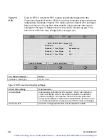
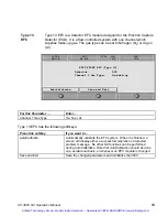
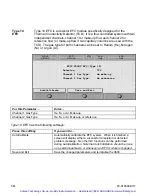
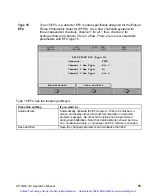
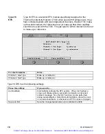
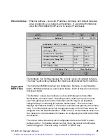
Type 1 EFC
This is the electronic flow control used for the CP-1177 and 1079 injectors, a
back-pressure regulated system with a split flow controller.
Type 1 EFC has the following parameters:
For this Parameter …
Enter…
Outlet Pressure
Atm if the column vents to atmospheric pressure
Vacuum if the column is connected to a vacuum source, e.g., a
mass spectrometer
Pressure Display Units
psi, bar, kPa, depending on which pressure units that you want to
display
Splitless Vent Flow
The flow the system will vent when the split valve is left closed for
the duration of the run such as during an on-column injection.
This flow is diverted before the injector and thus does not
influence the splitless nature of the run. This entry is ignored
during split and splitless runs in which the split vent is opened.
This parameter should not be set to less than 20 mL/min.
Gas Saver Flow
The lowest system flow rate that will be maintained during the gas
saver period. This has a range of 1-100 mL/min and defaults to
20 mL/min.
Gas Saver Timeout
A non-zero value entered for this parameter will cause the system
to initiate a timer once a method is activated. If no system actions
such as a run start or another method activation occurs before the
Gas Saver Timeout is reached; then the system will reduce the
flow through the system to the Gas Saver Flow. The GC will
advance to a faulted state (all three LEDs will be lit). A method
activation action will clear the Gas Saver Flow and bring the
system to Ready for subsequent injections. A zero value entered
for the Gas Saver Timeout will cause the Gas Saver Flow to be
ignored and no Gas Saver actions will be performed
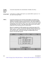
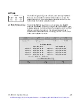
Type 1 EFC has the following softkeys:
Press this softkey
If you want to…
AutoCalibrate Automatically
calibrate the EFC system. When it is finished, a
screen will display either a successful completion or detected
problem message. No other GC functions can be performed
during AutoCalibration.
Note that AutoCalibration should be done
on a semiannual basis, or whenever an EFC module is changed.
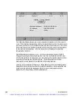
Septum Purge Calibrate
Calibrate the septum purge. After installing a new column, the
septum purge should be calibrated. Set the desired column head
pressure and press the “Enter” key. Then measure the actual
septum purge flow rate and enter this value in the septum purge
field. The septum purge flow rate is adjustable but is typically set
at 3 - 5 mL/min.
Save and Exit
Save the changed parameters and reinitialize the 3800.
Artisan Technology Group - Quality Instrumentation ... Guaranteed | (888) 88-SOURCE | www.artisantg.com


