background image

Summary of Contents for DATA 620/i

Page 1: ...DATA 620 i SYSTEM REFERENCE MANUAL...

Page 2: ...DATA 620 i SYSTEM REFERENCE MANUAL va ian data machines fa varian subsidiary 2722 michelson drive irvine california 92664 714 833 2400 C 1968 printed in USA...

Page 3: ...VDM 3000 Revision A March 1968...

Page 4: ...Organization 2 1 2 2 Computer Word Formats 2 6 2 3 Computer Options 2 11 SECTION 3 OPERATIONAL INSTRUCTIONS 3 1 General 3 1 3 2 Sing Ie Word Instructions 3 1 3 3 Double Word Instructions 3 31 SECTION...

Page 5: ...stem A 1 B Standard DATA 620 i Subroutines B 1 C Table of Powers of Two C 1 D Octal Decimal Integer Conversion Table D 1 E Octal Decimal Fraction Conversion Table E 1 F DATA 620 i Instructions Alphabe...

Page 6: ...ptional Up to 10 devi ces may be placed on the I O bus The I O system is easily expandable to include features such as automatic block tra nsfer pri ori ty in terru pt and cycle stealing data transfer...

Page 7: ...he DATA 620 i is enhanced by easy front access to all wiring making it unnecessary to remove panels on the computer rack to obtain access to the modu les con nectors and wiring A complete set of softw...

Page 8: ...l over load protection is standard Parallel binary fixed point 2 1 s complement Word Length Speed fetch and execute Add or Subtract 16 bits standard 18 bits optional 3 6 microseconds Multiply optional...

Page 9: ...x with X register hardware to 32 768 words does not add to execution time Index with B register hardware to 32 768 words does not add to execution ti me Multilevel indirect to 32 768 words Immediate o...

Page 10: ...le in groups of eight with group enable disable and individual arm disarm Each interrupt line is associated with a unique memory location 10 1 2 inches high 13 inches deep 90 pounds including power su...

Page 11: ...i subset of ASA FORTRAN for 8192 word memory Program analysis package which assists programmers in operating the machine and debugging other programs Includes basi c operationa I executive subroutines...

Page 12: ...inter Controller Reference Manua I 300 LPM Line Printer Controller Reference Manua I Paper Tape System Controller Reference Manual Priori ty Interrupt Reference Manua I A D Converter Reference Manua I...

Page 13: ...manufacturers reference manuals furnished with the equipment Section 2 of this manual contains an overall description of the DATA 620 i system and describes the word formats used in the computer Secti...

Page 14: ...on arithmetic logic secti on operationa I regi sters interna I buses input ou tput I O bus and memory 2 1 1 Control Section The control section provides the timing and control signals required to perf...

Page 15: ...UNIT 0 1l D 1 CONTROL FIRST E BUS VO 110 ARITHMETIC ADDER TTY INTERFACE DEVICE DEVICE LOGIC CONTROLLER OPTION OPTION t L 7 V C BUS C BUS SET L SETW_ SET A SET B 1 SET X SET 1 L W A B X P REGISTER REGI...

Page 16: ...gating required for all arith metic logic and shifting operations performed by the computer Indexed and relative address modifications are performed in this section without increased instruction exec...

Page 17: ...length register holds the address of the current instruction and is incremented before each new instruction is fetched A full complement of instructions is available for conditional and unconditional...

Page 18: ...s read from memory are transferred to the control section for execution Words may be transferred under program control from memory to the arithmetic logic section to the operational registers or to th...

Page 19: ...word length configuration of the particular machine In the 16 bit format the data occupy bit positions 0 14 with the sign in position 15 Negative numbers are represented in 2 1 s complement form In th...

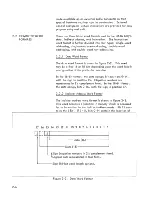
Page 20: ...cro seconds to the basic execution time of an instruction 2 2 3 Single Word Instruction Formats Single word instructions may be either addressing or non addressing as described in the following paragr...

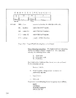
Page 21: ...d Addressing Instruction Format Non addressi ng instru cti ons The si ng Ie word non addressing instruction format is shown in figure 2 5 This instruction contains the following three fields C Class c...

Page 22: ...fi e Ids C Class code o Operation code D Definition The double word addressing instruction is shown in figure 2 6 This format is used for the following instruc tion types JUMP JUMP AND MARK EXECUTE E...

Page 23: ...the single word addressing instruc tions except that they allow direct addressing to 32 768 words of memory For the memory input output group the definition field of the first word contains the numbe...

Page 24: ...of a specified memory location The original contents of the A register are added to the final product Execution time is 18 microseconds for the basic 16 bit computer 19 8 microseconds for the l8 bit...

Page 25: ...does not require a stack heater This concept allows stack temperature to follow ambient temperature but compensate by control Iing drive circuits with a simple and unique electronic servo Th is servo...

Page 26: ...st interrupt can range from 100 Hz to 10 kHz or an externa I frequency source can be used Th is option is physically mounted in the DATA 620 i mainframe Direct memory access and interrupt must be inst...

Page 27: ...p of eight interrupt can be enabl ed disabled individually and contains an eight bit mask register that controls the individual inter rupt lines Acknowledgment of an interrupt by the computer causes t...

Page 28: ...ord and double word Each class contains both addressing and non addressing groups of instructions Microprogramming operations which can be implemented for various instruction types are summarized in a...

Page 29: ...ress Indexing does not increase the basic instruction execution time For indirect addressing the address field specifies the location of an indirect address word within the first 512 0 511 words of me...

Page 30: ...r I BRING I I OPERAND I 0N R 1 I EXECUTE I I INSTRUCTION I L __ _ J NO ADDRESS OPERAND U o_lO L YES ADDRESS INDIRECT ADDRESS Uo S L SET ADDRESS CYCLE BRING INDIRECT ADDRESS 0N R ADDRESS OPERAND R L YE...

Page 31: ...DX BRING INSTRUCTION W U FORM EFFECTIVE ADDRESS Fig 3 1 BRING OPERAND W R SET ADDRESS NEXT INSTRUCTION P 1 L P LOAD OPERAND R A B or X BRING NEXT INSTRUCTION W U Fig 3 2 Load Type Instruction General...

Page 32: ...TRUCTION W U FORM EFFECTIVE ADDRESS i Fig 3 1 SELECT A B I X AND TRANSFER TO MEMORY TO W w ADDRESS NEXT INSTRUCTION P l L P BRING NEXT INSTRUCTION W U Fig 3 3 Store Type Instruction GeneraI Flow P0131...

Page 33: ...Yes Indexing Yes Indirect Addressing Yes Registers Altered B Load Index Register Timing 2 cycles 17 16 15 14 13 12 11 10 9 8 7 6 5 4 3 2 0 f T 03 M A L _ J _ ______ _ _ _ _ _ _ _ _ _ _ _ lIS bit I op...

Page 34: ...direct Addressing Yes Registers Altered Memory Store Index Register Timing 2 cycles 17 16 15 14 13 12 11 10 9 8 7 6 5 4 3 2 0 r T 07 M A L _ J _ L _ _ _ _ _ J _ _ _ I _ _ _ _ _ _ _ _____ lIS bit I opt...

Page 35: ...N U BRING OPERAND N R INCREMENT OPERAND AND TRANSFER TO MEMORY ADDRESS NEXT INSTRUCTION P l L P BRING NEXT INSTRUCTION N U YES SET OVERFLOW OV l Fig 3 4 Increment Memory and Replace Instruction Gener...

Page 36: ...INSTRUCTION W U BRING OPERAND W R ADDRESS NEXT INSTRUCTION P l L P ADD OPERAND TO A SUB A R 1 A A R A BRING NEXT INSTRUCTION W U YES SET OVERFLOW OF 1 Fig 3 5 Add Instruction I Genera I Flow P013180S...

Page 37: ...Memory OF Add Memory to A Timing 2 cycles 17 16 15 14 13 12 11 10 9 8 7 6 5 4 3 2 1 0 T 12 M A L_ L _ I _ _ _ _ _ I _ _ _ L_ _ _ _ _ _ _ _ IIS bitl option The contents of the effective memory locatio...

Page 38: ...ffective memory location The original contents of the A register are added to the final product The product is placed in the A and B registers with the most significant half of the product in the A re...

Page 39: ...h instruction in the logical instruction group RA Indexing Yes Indirect Addressing Yes Registers Altered A B OF Inclusive OR Memory and A Timing 2 cycles 17 16 15 14 13 12 11 10 9 8 7 6 5 4 3 2 1 0 r...

Page 40: ...A register The result is placed in the A register If the same bit position of the effective memory location and A contain a zero or if both bit positions contain a one the result is zero If the same...

Page 41: ...ition Effective Memory A n Location n 0 a 0 1 1 a 1 1 Indexing Yes Indirect Addressing Yes Registers Altered A 3 2 2 Single Word Non Addressing Instructions Result A n 0 0 0 1 The format of the single...

Page 42: ...puter is placed in the step mode When the RUN button is pressed computation starts with the next instruction in sequence Indexi ng No Indirect Addressing No Registers Altered None N P No Operation Tim...

Page 43: ...ion format showing the use of each A field bit is given in table G 3 a appendix G Twelve of the possible sixteen shift operations defined by bits 5 8 are implemented These are summarized in table G 3...

Page 44: ...HIFT CONTROL ADDRESS NEXT INSTRUCTION P l L P INCREMENT SHIFT COUNTER SHIFT ONE III POSITION LOAD A 8 BRING NEXT INSTRUCTION NY U Fia 3 6 Sinal e Reaister Shift Instruction Genera I Flow P0131806A SET...

Page 45: ...ifted out of the low order position of tne B register is lost Zeros are shifted into the high order position of the B register Indexing No Indirect Addressing No Registers Altered B ILRLA I Logical Ro...

Page 46: ...nto bit position BO Indexing No Indirect Addressing No Long Logical Shift Right Timing 1 0 50 n cycles n number of sh ifts 17 16 15 14 13 12 11 10 9 8 7 6 5 4 3 2 1 0 r T 00 4 540 n L _ L_ _____ ___ L...

Page 47: ...nto bit position BO Indexing No Indirect Address No Registers Altered A B IASRA I Arithmetic Shift A Right Timing 1 0 25 n cycles n number of shifts 17 16 15 14 13 12 11 10 9 8 7 6 5 4 3 2 0 r T 00 4...

Page 48: ...s shifted out of A14 A16 are lost Indexing No Indirect Addressing No Registers Altered A IASRB I Arithmetic Shift B Right Timing 1 0 25 n cycles n number of shifts 17 16 15 14 13 12 11 10 9 8 7 6 5 4...

Page 49: ...No Indirect Addressing No ILASR I Long Arithmetic Shift Right Timing 1 0 50 n cycles n number of sh ifts 17 16 15 14 13 12 11 10 9 8 7 6 5 4 3 2 a 1 T 00 4 500 n L _ L _ L _ _ _ _ _ L_ _ _ I _ _ _ _ _...

Page 50: ...e operations in a single instruction The instruction format is shown in figure 3 7 The address fie Id A defines the source and destination of a parallel word transfer within the operational register s...

Page 51: ...plement 11 Decrement 10 Execute Unconditional 11 Execute Condition on Overflow Set Figure 3 7 Register Change Instruction Increment A Register Timing 17 16 15 14 13 12 11 10 9 8 7 6 5 4 3 2 T 00 5 111...

Page 52: ...ges from plus to minus the overflow indicator OF is set Indexing No Indirect Addressing No Registers Altered A B X OF Decrement A Register Tim ing cycle 17 16 15 14 13 12 11 10 987 6 5 4 3 2 1 0 r T L...

Page 53: ...t A Register Timing cycle 17 16 15 14 13 12 11 10 987 6 5 4 3 2 1 0 T 00 5 211 L_ L_ IIS bitl option Complement B Register Timing 1 cycle 17 16 15 14 13 12 11 10 987 6 543 2 0 r T 00 5 222 L_ L_ lIS b...

Page 54: ...egister to X Reg ister Timing 1 cycle 17 16 15 14 13 12 11 10 9 8 7 6 5 4 3 2 1 0 r T 00 5 014 L _ _ _ _ _ _ _ _ _ _ _ _ _ _ _ _ _ _ Ila bit I option The contents of the A register are placed in the X...

Page 55: ...ndexing No Indirect Addressing No Registers Altered X Transfer X Register to A Reg ister Timing 1 cycle 17 16 15 14 13 12 11 10 9 8 7 6 5 4 3 2 1 0 00 5 041 L_ J _ _____ ____ I_ _ _ _ _ _ _ lIS bit I...

Page 56: ...on Transfer Zero to X Regi ster 17 16 15 14 13 12 11 10 9 8 7 6 T L_ J _ 00 5 Ila bitl option The A B X register is cleared to zero Indexing No Indirect Addressing No Registers Altered A B X Timing cy...

Page 57: ...ents of the overflow indicator OF are added to the A B X register mod 2 16 2 18 The sum is placed in the A B X register The overflow fl ip flop does not change S FA Indexing No Indirect Addressing No...

Page 58: ...is contained in the memory location following the instruction word The second word may contain an operand or an address The address may be either indirect or direct The general flow chart for double w...

Page 59: ...STRUCTION _I_ _ _ I W U 1 L ______ J YES YES SET ADDRESS CYCLE BRING ADDRESS W R NO Fig 3 8 Double Word Instruction General Flow SINGLE WORD INSTRUCTION SET OPERAND CYCLE BRING OPERAND W R EXECUTE INS...

Page 60: ...6 5 4 3 2 1 0 r T I I r I I r l bit option 00 1 I 000 I I Jump Address The next instruction executed is at the jump address Indexing No Indirect Addressing Yes Registers Altered P Jump if Overflow Ind...

Page 61: ...G INSTRUCTION W U ADDRESS JUMP ADDRESS P 1 L P BRING JUMP ADDRESS W R SET JUMP ADDRESS R L P BRING NEXT INSTRUCTION W U YES NO ADDRESS INDIRECT ADDRESS R L BRING INDIRECT ADDRESS W R RESET OF IF OVERF...

Page 62: ...is negative the next instruction in sequence is executed IJAN I 17 16 r r I I I I Indexing No Indirect Addressing Yes Registers Altered P Jump if A Register Negative 15 14 13 12 11 10 9 8 00 I I Timi...

Page 63: ...not zero the next instruction in sequence is executed 17 16 r T I I 1 I I Indexing No Indirect Addressing Yes Registers Altered P Jump if B Register Zero 15 14 13 12 11 10 9 8 7 00 I I 6 I I Jump Addr...

Page 64: ...e jump address If the register is not zero the next instruction in sequence is executed 17 16 r r 1 I I Indexing No Ind irect Addressing Yes Registers Altered P Jump if Sense Switch 1 Set 15 14 13 12...

Page 65: ...set of logical conditions specified for the jump group These conditions are summarized in table G 6 a in appendix G Thus there are 512 possible combinations but not all are useful The most convenient...

Page 66: ...S NO MARK R 15 1 LOCATION R L YES ADDRESS STORE NEXT RETURN INSTRUCTION ADDRESS P 1 L P ADDRESS P 1 W INDIRECT ADDRESS R L ADDRESS MARK 1 INSTRUCTION R l L P BRING INDIRECT ADDRESS r W R BRING BRING N...

Page 67: ...e overflow indicator is not set the next instruction in sequence is executed The overflow indi cator is reset upon execution of the JOFM instruction Indexing No Indirect Addressing Yes Registers Alter...

Page 68: ...s executed If the A register is negative the next instruction in sequence is executed Indexing No Indirect Addressing Yes Registers Altered Jump address P JAZM Jump and Mark if A Timing 2 3 cycles Reg...

Page 69: ...instruction in sequence is executed Indexing No Indirect Addressing Yes Registers AI tered Jump address P IJXZM I Jump and Mark if X Timing 2 3 cycles Register Zero 17 16 15 14 13 12 11 10 9 8 7 6 5 4...

Page 70: ...I I I I Jump Address 1 _ 1a l optIon JS3M Jump and Mark if Sense Timing 2 3 cycles Switch 3 Set 17 16 15 14 13 12 11 10 9 a 7 6 543 2 1 0 r T I I I I 00 2 400 I I I I Jump Address L la bit optIon If...

Page 71: ...ed by the DAS assembler summarized in table G 7 b Figure 3 11 illustrates the general flow for the execute instructions It is important to note that only single word instructions should be executed Th...

Page 72: ...TION MET NO INDIRECT ADDRESS R15 1 YES ADDRESS ADDRESS ADDRESS NEXT EXECUTE INDIRECT INSTRUCTION INSTRUCTION ADDRESS P l L P R L R L r BRING BRING BRING NEXT EXECUTE INDIRECT INSTRUCTION INSTRUCTION A...

Page 73: ...is executed Execution of the XOF instruction resets the overflow indi cator IXAP I 17 16 r r I I I I Indexing No Indirect Addressing Yes Registers Altered OF reset Execute if A Regi ster Positive 15...

Page 74: ...itive the next instruction in sequence is executed XAZ Indexi ng No Indirect Addressing Yes Registers Altered None Execute if A Register Zero Timing 2 cycles 17 16 15 14 13 12 11 10 9 8 7 6 5 4 3 2 1...

Page 75: ...o the next instruction in sequence is executed Indexing No Indirect Addressing Yes Registers Altered None Ixxz I Execute if X Regi ster Zero 17 16 15 14 13 12 11 10 9 8 r T I I I I 00 3 7 6 I I I I Ex...

Page 76: ...3 200 I I I I Execute Address G L 18 b option Execute if Sense Switch 3 Tim ing 2 cycles 17 16 15 14 13 12 11 10 9 8 7 6 543 2 1 0 r T I I I I 00 3 400 1 4 I I I I Execute Address _L 18 b option If se...

Page 77: ...single word instruction in the op code Effective Address Second word contains operand Contents of second word plus P register plus 1 Contents of second word plus X register Contents of second word pl...

Page 78: ...s at location n 1 are placed in the B register LDXE 17 16 r r I I I I l8 bit Indexing Yes Indirect Addressing Yes Register Altered B Load X Register Extended optiona I 15 14 13 12 11 10 9 8 7 6 5 00 I...

Page 79: ...dressed by the operand address at location n 1 STBE Indexing Yes Indirect Addressing Yes Register Altered Memory Store B Register Extended optional Timing 3 cycles 17 16 15 14 13 12 11 10 9 8 7 6 5 4...

Page 80: ...n 1 Indexing Yes Indirect Addressing Yes Register Altered Memory INRE Increment Memory and Timing 4 cycles Replace Extended optional 17 16 15 14 13 12 11 10 9 8 7 6 5 4 3 2 1 0 r T 00 I 6 I 04 I X I I...

Page 81: ...e overflow indicator OF is set SUBE Indexing Yes Indirect Addressing Yes Register Altered A OF Subtract Memory from A Extended optional Timing 3 cycles 15 14 13 12 11 10 9 8 7 6 5 4 3 2 1 0 17 16 r r...

Page 82: ...the least significant half in the B register The sign of the product is contained in the sign position of the A regi ster The sign position of the B regi ster is reset to zero The a Igorithm is in the...

Page 83: ...I I J _ L ll8 bit I Operand Address option The inclusive OR operation is performed between the contents of the A register and the contents of the memory location as addressed by the operand address i...

Page 84: ...contents of the memory location as addressed by the operand address in location n 1 The resu It is placed in the A register If the same bit position of the memory location and the A register contains...

Page 85: ...ion and the A register contains a one the result is a one The truth table is shown below where n bit position Condition Effective A n Memory Location n 0 0 0 1 1 0 1 1 Indexing Yes Indirect Addressing...

Page 86: ...and at location n 1 are placed in the A register LOBI 17 16 r T I I I I 18 bit Indexing No Indirect Addressing No Registers Altered A 15 Load B Register Immediate 14 13 12 11 10 00 I 6 9 8 I Operand L...

Page 87: ...perand at location n 1 are placed in the X register Indexing No Indirect Addressing No Registers Altered X Store A Register Immediate 17 16 15 14 13 12 11 10 r r I I I 00 6 9 8 I I I Operand L_ 18 b l...

Page 88: ...ced in the operand at location n 1 ISTXI I 17 16 r T I I I I L_ 18 bit option Indexing No Ind irect Addressing No Registers Altered Operand Store X Register Immediate 15 14 13 12 11 10 9 8 00 I 6 I Op...

Page 89: ...15 _2 17 the overflow indi cator OF is set SUBI 17 16 r T I I 1 I I Indexing No Indirect Addressing No Registers Altered A OF Subtract Immediate 15 14 13 12 11 10 9 8 00 I 6 I Operand _L 18 bi option...

Page 90: ...nt half in the B register The sign of the product is contained in the sign position of the A register The sign position of the B register is reset to zero The algorithm is in the form R B A Indexing N...

Page 91: ...216 21 After execution if n 1 2 15 217 the overflow indi cator OF is set Indexing No Indirect Addressing No Registers Altered Operand OF Exclusive OR Immediate Timing 2 cycles 17 16 15 14 13 12 11 10...

Page 92: ...1 0 110 An inclusive OR is performed between the contents of the operand and the contents of the A register The result is placed in the A register If either the operand or the A register con tains a o...

Page 93: ...ents of the operand and the contents of the A register The result is placed in the A register If the same bit position of the operand and the A register contains a one the result is one otherwise the...

Page 94: ...the operational registers and the memory through the internal C bus Data and control signals are transmitted to and from external peripheral devices through the I O bus 4 2 1 Overa II Operation The o...

Page 95: ...ARDWIRE fJ EXEC PROGRAM INTERRUPT CABLE 1 BUFFER 1 4 INTERLACE 2 PRIORITY HIGH CONTROLLER INTERRUPTS SPEED PLOTTER BIC N PRINTER I I O CABLE TTY TAPE AID CONTROLLER CONVERTER T B CABLE I J TRANSPORT T...

Page 96: ...4 2 3 Input Output Operations During information transfers over the I O bus the E bus lines may carry control codes addresses or data dependi ng upon the type of operation being performed Table 4 1 d...

Page 97: ...nd 3 PR2X I PR3X I Interrupt Jump IUJP I 4 4 Function Indicates a demand from the Interrupt module to force pro gram to take one instruction from location specified by address on E bus Th is address...

Page 98: ...ission to the peripheral controllers The device address is contained in the YY portion of the data and the function to be performed by the selected device is contained in the X portion Indexing No Ind...

Page 99: ...ADDRESS NEXT INSTRUCTION P l L P ADDRESS JUMP ADDRESS P l L R NO BRING NEXT INSTRUCTION W U TRANSFER t ____a SENSE CODE YES Uo U8 E BUS FORM EFFECTIVE ADDRESS FIG 3 8 R L R BRING INSTRUCTION W U Fig...

Page 100: ...g Yes Regi sters A Itered P 4 3 3 Data Transfer In Two types of data transfer in instructions are provided input to operational registers and input directly to memory The first type of input instructi...

Page 101: ...ster Timing 2 cycles 17 16 15 14 13 12 11 10 9 8 7 6 5 4 3 2 0 T 10 2 lZZ L_ L _ _ _ _ _ _ _ _ _ _ _ _ _ _ _ _ _ _ lIB bit I option A data word from the selected device ZZ is inclusively OR led with t...

Page 102: ...sters A Itered Memory 4 3 4 Data Transfer Ou t Two types of output data transfer instructions are provided output from operationa I registers and output from memory The first type of instruction is a...

Page 103: ...ND ADDRESS W R ADDRESS NEXT INSTRUCTION P l L P P0131813A ADDRESS TRANSFER OPERAND DEVICE ADDRESS CODE P 1 L P U U E o 5 BUS FORM EFFECTIVE INPUT DATA ADDRESS FIG 3 8 E BUS W BRING NEXT INSTRUCTION VV...

Page 104: ...14 13 12 11 10 9 8 7 6 543 2 1 0 r T I I I I 10 3 OZZ r I I I I Da ta Address L_ 18 bi option The contents of the effective memory location are transferred to the selected device ZZ Indexing No Indir...

Page 105: ...al program operation This type of operation uses the computer trap timing sequence to delay the program for 2 7 microseconds whi Ie a word is transferred between memory and a peripheral device The tra...

Page 106: ...TRAP REQUEST ACKNOW LEDGE REQUEST INPUT TRAP ADDRESS INPUT OUTPUT DATA TRAP COMPLETE t 1 8 5 MIN 5 4 S MAX HIGHER PRIORITY SERVICE DELAY r 2 7 5 Fig 4 4 Trap Sequence General Flow P0131814A 4 13...

Page 107: ...e interrupt system The action initiated by an interrupt subrou tine causes the interrupting devi ce to remove its request signal An acknowledgment of an interrupt causes the instruction located at the...

Page 108: ...ble control flexibility and are useful for maintenance troubleshooting and program debugging The sense switches are useful in normal program operation to allow selection of particular program sequence...

Page 109: ...P0131815A DATA aO i Fig 5 1 Control Console...

Page 110: ...or lights when a thermal overload condition occurs The RESET switch causes the selected register to be cleared This switch is disabled when the computer is in the run mode The STEP switch is a momenta...

Page 111: ...itch is pressed the instruction contained in the instruction register is executed and the instruction of the selected address is transferred to the instruction register Repeated operation of the STEP...

Page 112: ...register for each step To display the contents of a group of sequential memory cells set the appropriate load type instruction LOA LOB LDX in the instruction register in the relative address mode wit...

Page 113: ...APPENDICES...

Page 114: ...Appendix A OATA 620 i Number System...

Page 115: ...mplement each bit add 111 in the least significant bit position Example 9 0000000000001001 lis complement 1111111111110110 1 2l s complement 111111111111 0111 9 b For an n bit number including sign su...

Page 116: ...0 0 1111111111111111 1777778 1 1 1000000000000000 100000 8 32 768 Full Scale The negative of the octal equiva lent number is found by subtracting the number from 1777778 and adding 1 in the least sig...

Page 117: ...anges when two numbers of the same sign are added together where the sign of the subtrahend is changed in subtraction In multiplication a double length product is formed in the arithmetic registers A...

Page 118: ...Appendix B Standard DATA 620 i Subroutines...

Page 119: ...1 to 1 15 380 usee Single Precision fixed point Mu Iti ply optiona I hardware 18 usee Divide optional hardware 27 usee Divide programmed 27 300 usee Double Precision fixed point Open Addition 7 20 us...

Page 120: ...Subroutines Locations Time Conversion Binary ta BCD 4 characters 32 249 usec BCD to Binary 28 205 usec B 2...

Page 121: ...Appendix C Table of Powers of Two...

Page 122: ...25 0 000 000 029 802 322 387 695 312 5 67 108 864 26 0 000 000 014 901 161 193 847 656 25 134 217 728 27 0 000 000 007 450 580 596 923 828 125 268 435 456 28 0 000 000 003 725 290 298 461 914 062 5 53...

Page 123: ...Appendix D Octal Decimal Integer Conversion Table...

Page 124: ...98 0599 1520 0848 0849 0600 0601 0602 0603 0604 0605 0606 0607 1530 0856 0857 0608 0609 0610 0611 0612 0613 0614 0615 1540 0864 0865 0616 0617 0618 0619 0620 0621 0622 0623 1550 0872 0873 0624 0625 06...

Page 125: ...1413 1414 1165 1166 1167 2610 1416 1417 1418 1419 1420 1421 1422 1173 1174 1175 2620 1424 1425 1426 1427 1428 1429 1430 11111 1182 1183 2630 1432 1433 1434 1435 1436 1437 1438 1189 1190 1191 2640 144...

Page 126: ...4 2255 4710 2504 2505 2506 2507 2508 2509 2510 2511 2257 2258 2259 2260 2261 2262 2263 4720 2512 2513 2514 2515 2516 2517 2518 2519 2265 2266 2267 2268 2269 2270 2271 4730 2520 2521 2522 2523 2524 252...

Page 127: ...1 3462 3213 3214 3215 6610 3464 3465 3466 3467 3468 3469 3470 3221 3222 3223 6620 3472 3473 3474 3475 3476 3477 3478 32 9 3230 3231 6630 3480 481 3482 3483 3484 3485 3486 3237 3238 3239 6640 3488 3489...

Page 128: ...Appendix E Octal Decimal Fraction Conversion Table...

Page 129: ...29687 1135 056640 135 181640 235 306640 335 431640 036 058593 136 183593 236 308593 336 433593 037 060546 137 185546 237 310546 337 435546 040 062500 140 187500 240 312500 340 437500 041 064453 141 18...

Page 130: ...5 000598 000335 000843 000036 000114 000136 000358 000236 000602 000336 000846 000037 000118 000137 000362 000237 000606 000337 000850 000040 000122 000140 000366 000240 000610 000340 000854 000041 00...

Page 131: ...635 001575 000735 001819 000436 001091 000536 001335 000636 001579 000736 001823 000437 001094 000537 001338 000637 001583 000737 001827 000440 001098 000540 001342 000640 001586 000740 001831 000441...

Page 132: ...Appendix F DATA 620 i Instructions Alphabetical Order...

Page 133: ...Add OF to B Register 1 1 No A FX 005544 Add OF to X Register 1 1 No AS LA 004200 n Arithmetic Shift Left A n 1 1 0 25n No Places ASLB 004000 n Ari thmetic Shift Left B n 1 1 0025n No Places ASRA 0043...

Page 134: ...06130 Exc Iusive OR to A Register 2 2 No Immediate EXC 100000 Externa I Control Function 1 1 No HLT 000000 Halt 1 1 No JAR 005111 Increment A Register 1 1 No IBR 005122 Increment B Register 1 1 No IME...

Page 135: ...es Unconditionally J F 001001 Jump if Overflow On 2 2 Yes J FM 002001 Jump and Mark if Overflow 2 2 3 Yes On JS1M 002100 Jump and Mark if Sense 2 2 3 Yes Switch 1 On JS2M 002200 Jump and Mark if Sense...

Page 136: ...ical Rotate Left 1 1 0 50n No n Places LLSR 004540 n Long Logical Sh ift Right 1 1 0 50n No n Places LRLA 004240 n Logical Rotate Left A nPlaces 1 1 0 25n No LRLB 004040 n Logical Rotate Left B n Plac...

Page 137: ...gister S FB 005722 Subtract OFLO from B 1 1 No Register S FX 005744 Subtract OFLO from X 1 1 No Reg ister STA 050000 Store A Register 1 2 Yes STAE 006050 Store A Register Extended 2 3 Yes STAI 006050...

Page 138: ...fer Zero to A Reg ister 1 1 No TZB 005002 Transfer Zero to B Register 1 1 No TZX 005004 Transfer Zero to X Register 1 1 No XAN 003004 Execute A Register Negative 2 2 Yes XAP 003002 Execute A Register...

Page 139: ...Appendix G DATA 620 i Instructions By Type...

Page 140: ...Load B Register LDX Load X Register STA Store A Reg ister STB Store B Register STX Store X Register Table G 1 b Arithmetic Instruction Group Op Code Mnemonic Instruction INR Increment and Replace ADD...

Page 141: ...ssing Operation 11 10 9 Mode a x X Direct Combine bits 9 10 with a field 0 8 to form effective address 0000 2047 1 0 a Relative Add a fiel d bits 0 8 to contents of P to form effective address Mod 215...

Page 142: ...S F Octal M Field U 8 0 A or B 1 A B M A Field Field Instruction 0 XXX Halt 5 000 No Operation 7 400 Reset Overflow 7 401 Set Overflow Table G 3 Shift Instruction Group Table G 3 a Instruction Format...

Page 143: ...ong Arithmetic Shift A B Left Long Logical Rotate A B Registers Left Long Arithmetic Shift A BRight Long Logical ShiftI AI B Registers Invalid Invalid Inval id Inval id Table G 4 Timing Cycles 1 O 25n...

Page 144: ...ansfer B Register to X Register 1 041 TXA Transfer X Register to A Register 1 042 TXB Transfer X Register to B Register 1 1 1 1 JAR Increment A Register 1 122 IBR Increment B Register 1 144 IXR Increm...

Page 145: ...000 JMP 001 J9 F 002 JAP 004 JAN 010 JAZ 020 JBZ 040 JXZ 100 JSSl 200 JSS2 400 JSS3 Table G 5 b Jump Instruction Codes Jump Instruction Jump Unconditionally Jump If Overflow Set Jump If A Register Pos...

Page 146: ...6 b Jump and Mark Instruction Codes Jump and Mark Instructions Jump and Mark Unconditionally Jump and Mark if Overflow Set Jump and Mark if A Register Negative Jump and Mark if A Register Positive Ju...

Page 147: ...gle word A Field Octal Mnemonic 000 XEC 001 X F 002 XAP 004 XAN 010 XAZ 020 XBZ 040 XXZ 100 XS 1 200 XS2 400 XS3 Table G 7 a Instruction Format Execute Instruction Execute Unconditionally Execute if O...

Page 148: ...Load A Immediate 6 020 Load B Immediate 6 030 Load X Immediate 6 040 Increment and Replace Immediate 6 050 Store A Immediate 6 060 Store B Immed iate 6 070 Store X Immediate 6 110 Inclusive OR Immedi...

Page 149: ...tal M Field A Field Instruction 0 XZZ External Control 1 XZZ Program Sense 2 OZZ Input to Memory 2 1ZZ Input to A 2 2ZZ Input to B 2 5ZZ Clear and Input to A 2 6ZZ Clear and Input to B 3 OZZ Output fr...

Page 150: ...00 STBE 6 06X Store B Register Extended 3 00 STXE 6 07X Store X Register Extended 3 00 INRE 6 04X Increment and Replace 4 Extended 00 ADDE 6 12X Add Memory to A Reg ister 3 Extended 00 SUBE 6 14X Sub...

Page 151: ...Appendix H DATA 620 i Reserved Instruction Codes...

Page 152: ...r interrupt modules Mnemonic Octal Function A Externa I Control EXC 140 100140 Clear AC Register EXC 240 100240 Enable Interrupt Module EXC 440 100440 Inhibit Interrupt Module EXC 540 100540 Initial i...

Page 153: ...A BR 20 103220 Load Initial Register from B ME 20 103020 Load Initial Register from Memory AR 21 103121 Load Final Register from A BR 21 103221 Load Final Register from B ME 21 103021 Load Final Regis...

Page 154: ...100 Transfer A Register to TTY Buffer OBR 00 103200 Transfer BRegister to TTY Buffer OME 00 103000 Transfer Memory to TTY Buffer INA 00 102100 Transfer TTY Buffer to A Register INB 00 102200 Transfer...

Page 155: ...01 102001 Transfer Read Register to Memory Register CIA 01 102501 Transfer Read Register to Cleared A Register CIB 01 102601 Transfer Read Register to Cleared B Register C Sense SEN 101 101101 Write R...

Page 156: ...ion A External Control EXC 230 100230 Read One Card EXC 630 100630 Step Read One Character B Transfer INA 30 102130 Transfer to A Register INB 30 102230 Transfer to B Register IME 30 102030 Transfer t...

Page 157: ...at the time of system definition Mnemonic Octal Function A External Control None B Transfer INA 60 102160 Input from Channe I to A Register INB 60 102260 Input from Channel to B Register ME 60 102060...

Page 158: ...at the time of system definition Mnemonic Octal Function A External Control None B Transfer INA 62 102162 Input from Channel to A Register INB 62 102262 Input from Channel to B Register IME 62 102062...

Page 159: ...rom B Reg ister through Channe I 103060 Output from Memory through Channel 101260 Sense Data Req uest Table H 8 Buffer Output Channel Reserved Instruction Code The following codes are for use with the...

Page 160: ...100037 Connect Punch to BIC EXC 437 100437 Stop Reader EXC 537 100537 Start Reader EXC 637 100637 Punch Buffer EXC 737 100737 Read 0 ne Charac ter B Transfer OAR 37 103137 Load Buffer from A Register...

Page 161: ...0 Backspace One Record EXC 710 100710 Rewind B Transfer AR 10 103110 Load Buffer from A Register BR 10 103210 Load Buffer from B Register ME 10 103010 Load Buffer from Memory INA 10 102110 Read Buffer...

Page 162: ...Appendix I Standard Character Codes...

Page 163: ...4 16 E 305 05 65 12 5 17 F 306 06 66 12 6 20 G 307 07 67 12 7 21 H 310 10 70 12 8 22 I 311 11 71 12 9 23 J 312 12 41 11 1 24 K 313 13 42 11 2 25 L 314 14 43 11 3 26 M 315 15 44 11 4 27 N 316 16 45 11...

Page 164: ...35 35 55 11 5 8 76 t 336 36 17 7 8 76 Note 337 37 20 2 8 761 blank 240 40 20 No Punch 00 241 41 52 11 2 8 51 II 242 42 35 0 5 8 62 243 43 37 0 7 8 63 244 44 53 11 3 8 60 0 0 245 45 57 11 7 8 64 246 46...

Page 165: ...2 72 i 273 73 274 74 275 75 276 76 277 77 Note End of file for mag tape Undefined character 1 Form control Return to coil 2 Tab control Skip to col 7 Mag Tape Hollerith 12 0 01 1 02 2 03 3 04 4 05 5 0...

Page 166: ...k 240 3 263 241 4 264 I 242 5 265 243 6 266 244 7 267 0 0 245 8 270 246 9 271 I 247 A 301 250 B 302 251 C 303 252 D 304 253 E 305 254 F 306 255 G 307 256 H 310 257 I 311 272 J 312 273 K 313 274 L 314...

Page 167: ...l Code Character Internal Code EOM 203 X OFF 223 EOT 204 TAPE OFF WRU 205 AUX 224 RU 206 ERROR 225 BEL 207 5YNC 226 FE 210 LEM 227 H TAB 211 50 230 LIN E FEED 212 51 231 V TAB 213 52 232 FORM 214 53 2...

Page 168: ......
Reviews: