DOC: 03-925862-00
DESC:
PAGE:
REV
1 of 2
3800GC W/DEFC Leak Test Procedure
1
PREPARED BY: Sax Makthepharack REVISED BY:
CONTROL: INDUSTRIAL ENGINEERING
REV. DATE:
SHOWN
-
06 - 09 - 98
Michael Slaughter
INJECTOR EFC LEAK TEST PROCEDURE
1.
Install
ETS
software Version 1.6.2 or newer. (be sure to discharge yourself before touching ROM pwa.)
2.
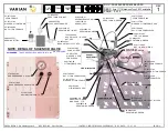
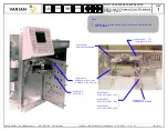
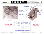
Set the DIP Switches on the main board as shown:
3.
Turn on power and connect Carrier Gas inlet tube.
4.
Make sure jumpers on EFC board are in the correct position.
5.
Cap off all unused gas inlet fittings and the Injector column out fitting.
6.
Press
MENU
key.
7.
Check com board if installed (under AOC cont.) pg.2.
8.
Check Detector Electrometer pwa’s, (3) are they present?.
9.
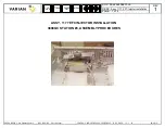
Check EFC’s, (5) are they present? Are they good?
10.
If EFC’s are present and good, press
Enter
Key and set to
Pressure DAC 5.00
and
Flow DAC to 3.00
.(Left blue toggle key below display 3
times to pressure up instrument).
11.
After completing items 1 thru 10, turn on Carrier Gas.
12.
When the pressure is stable, turn
OFF
Carrier Gas and press
LEAKSTOP
Key. (blue key below display)
13.
The leak test procedure will run for 5 minutes then stop and display the leak value for the 5 min. period. (< .30 + .10 for each EFC installed is
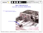
the acceptance criteria, (if the test fails, retest and measure the flow at the EFC Vent tube. If a leak is detected and is less than .10 ml/min.
subtract the amount from your total leak value. If that value is less than the spec (above), the instrument passed the test. If over, the
instrument Fail and the leak must be found and corrected. Retest as above until a pass condition is reached.
14.
Record the resulting value of the leak test on the QC Record Sheet.
15.
Press Menu Key, go to
TEMPERATURE MENU
(4) check and press
Enter
.
16.
Set all Temp zones to
NOT USED
and press
Enter
. (use
decrease
key)
17.
Go to Pg.2 of 3, check Vent Doors for unrestricted opening and closing. (toggle
ON
enter,
OFF
enter)
18.
If any Cryo is installed, go to pg. 3. Select the proper external event then activate to assure opening and closing. (blue Time Off/On key
under display)
19.
Go back to pg. 1 and Enable those zones used. Observe temperature go to 50 deg. and hold stable.
20.
Press CONTACTOR key.
21.
If Fan is running, go back to pg. 2 and turn off Fan.
22.
Go to EFC Control (5) enter, select flow key and measure each Inj/Det. for some amount of flow.
23.
Go to Main Menu, select EFC Control, press enter, go to EFC location (front, middle, rear) then go to pg. 6. In lower right corner of display
see EFC type, is it correct? (type 1,3,4,5, etc.) Turn Instrument Off, replace ROM board and restart instrument. Initial Display should
appear.

