background image

Introduction and Initial Operation 

Page 18  

User Manual Micro-GC 


Varian, Inc. 


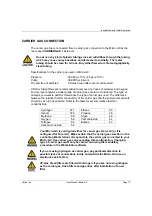
HEATED SAMPLE LINE 


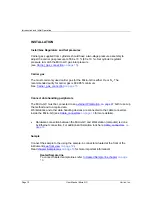
A heated sample line is always combined with a heated injector. 
A heated injector and sample line is an option for a channel unit and is chosen in case 
condensable samples need to be analyzed and condensation in the sample lines needs to be 
prevented.  
The heated sample and injector can be controlled between 30°C and 110°C. 
 

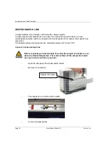
Connect a heated sample line 


Before connecting a heated sample line, allow the sample line heater to cool 
down to ambient temperature. The metal surfaces of the sample line heater 
are very hot and could burn your skin. 


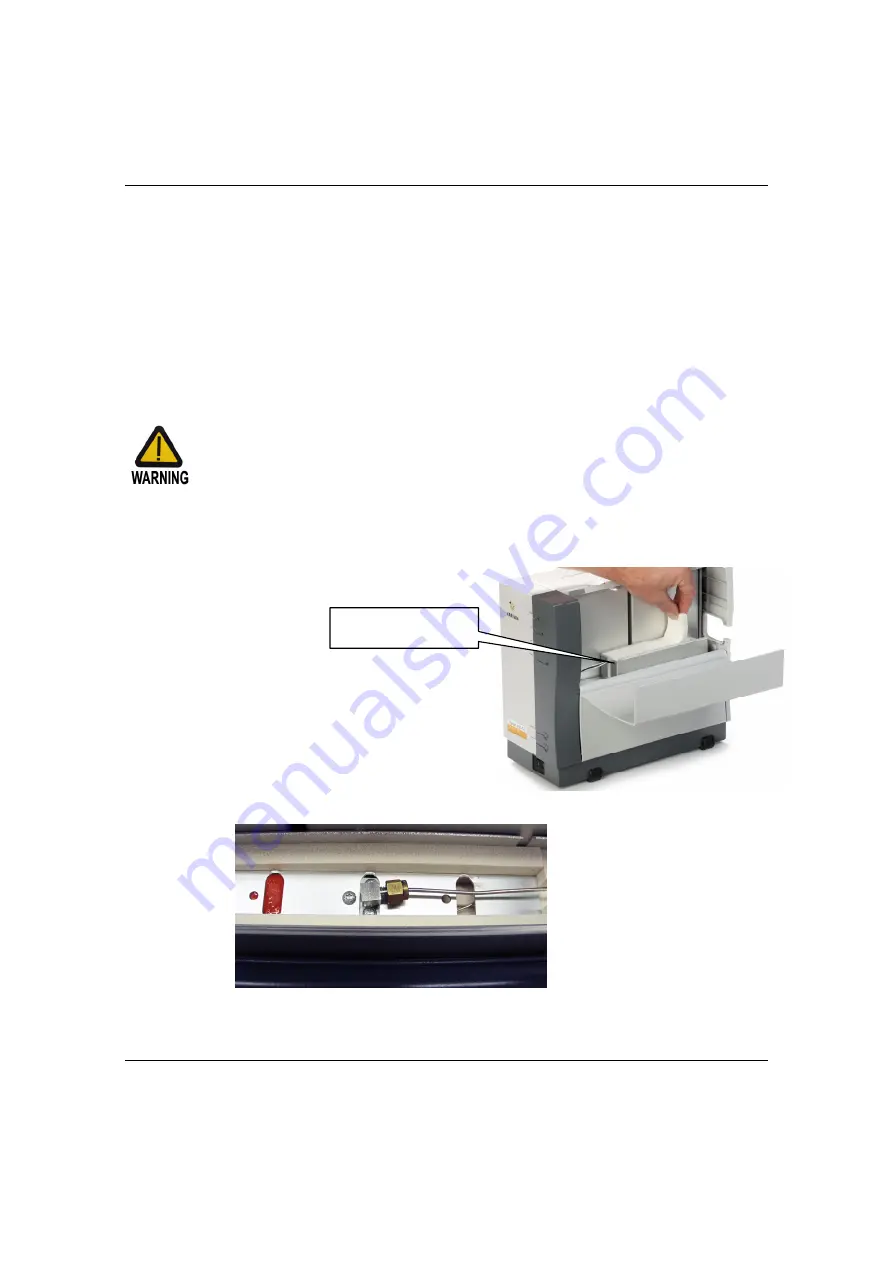
Open the side panel, the heater will be visible. 


Remove the insulation. 


The sample line connector will be visible. 


Connect the sample line. 


Sample line heater 

Summary of Contents for Micro-GC 490-GC

Page 1: ...ia USA Tel 1 9259392400 Fax 1 9259452360 or 1 9259452344 Europe P O Box 8033 4330 EA Middelburg The Netherlands Tel 31 118671000 Fax 31 118623193 Australia East Asia 679 Springvale Road Mulgrave Victo...

Page 2: ...le portion of the purchase price of the instrument or accessory Repair or replacement under warranty does not extend the original warranty period Repair or replacement under warranty claims shall be m...

Page 3: ...ea is likely to case harmful interference in witch case the user will be required to correct the interference at his own expense To prevent any injury to the user or any damage to the instrument it is...

Page 4: ...ge terminals fed from the interior by voltage exceeding 1000V must be so marked Indicates parts that may cause burns when touched Indicates that the user should refer to the manual before operating th...

Page 5: ...ropriate gases and or solvents and within specified maximum ranges for pressure flows and temperatures as described in this manual If the equipment is used in a manner not specified by the manufacture...

Page 6: ...Be sure to be familiar with and to follow accurately the operation procedures prescribed for those gases before operating the instrument 13 Never try to repair or replace any component that is not des...

Page 7: ...and material basis Technical support and training can be provided by qualified personnel on both a contractual or as needed basis Varian Analytical Instruments Sales Offices For Sales or Service assi...

Page 8: ......

Page 9: ...PARE PARTS AVAILABILITY VII SERVICE AVAILABILITY VII TABLE OF CONTENTS 1 PREPARING FOR INSTALLATION 6 GAS SUPPLY 6 GAS SAMPLES 6 MICRO GC INSTALLATION 7 INSPECTION 7 UNPACKING 7 PACKING LIST 8 Micro G...

Page 10: ...COLUMN CP SIL13CB TBM 12 METER HEATED 26 COLUMN HAYESEP 40CM HEATED 27 COLUMN MOLSIEVE 5 20 METER UNHEATED 28 Conditioning of Molsieve columns 29 COLUMN PPQ 10 METER HEATED 30 REFERENCE 31 INSTRUMENT...

Page 11: ...to peer single instrument 50 Multiple instrument local network 51 Global network Multiple instruments 52 COMMUNICATION SETUP 53 Serial communication EZCrom only 53 Ethernet communication Galaxie 53 AS...

Page 12: ...Table of contents Page 4 User Manual Micro GC Varian Inc SHIPPING INSTRUCTIONS 71 CLEANING INSTRUCTIONS 71 DISPOSAL INSTRUCTIONS 71 ERROR LIST 72 ERROR HANDLING 72 ERROR LIST 73...

Page 13: ...the allow column head pressure settings to become part of the GC method and can be programmed electronically The Varian Inc Micro GC with Micro EGC allows you to optimize your analysis Apart from the...

Page 14: ...Installation requirements Micro GC CP501289 GAS SAMPLES Do not introduce liquid samples into your Micro GC Type of samples non condensing gas Samples other than non condensing gases wet vapors particl...

Page 15: ...ce UNPACKING Unpack the Micro GC and accessories carefully and transfer to the work area using proper handling techniques Inspect the Micro GC and accessories carefully for damage or signs of rough ha...

Page 16: ...ter kit CP736729 Filters 5x for external filter assy CP736467 CD ROM user manual Micro GC CP505532490 Ethernet cross over cable 2 8 m CP740292 Locking nut CP420200 x 4 Male Luer CP420100 x 4 Front and...

Page 17: ...40292 Combo card Ethernet and Com ports including 3 meter crossover cable not for HUB 1 CP740292 Aux power car cigarette lighter DC adapter 1 CP740291 Charger for battery pack 1 CP740427 Battery pack...

Page 18: ...ect data handling peripherals The Micro GC must be connected to an external Workstation on page 47 both to set up the method and to acquire data Workstations and other data handling devices are connec...

Page 19: ...tes and settings When the Micro GC is turned on the power LED will light up and the system will begin the Flush cycle procedure The Flush cycle is a 2 minute cycle in which the various valves are acti...

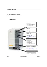
Page 20: ...POWER led Led OFF No power Led ON Power OK Led blinking Voltage 10 Volt SAMPLE 1 and SAMPLE 2 Sample gas inlet connector See here for more details on page 16 POWER ON OFF SWITCH Switch the Micro GC ON...

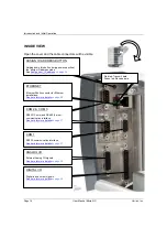
Page 21: ...on page 15 BACK VIEW POWER CONNECTOR Power IN connector male See here for more details on page 20 VENTS It is possible to connect long vent lines to these fittings in order to safely guide hazardous...

Page 22: ...face See here for more details on page 37 ANALOG I O External Analog I O signals See here for more details on page 38 DIGITAL I O Digital in and output signals See here for more details on page 36 ETH...

Page 23: ...s used The difference between the relative thermal conductivity of the carrier gas and the sample components should be as high as possible Refer to the table for several relative thermal conductivitie...

Page 24: ...al filter kit part number CP736729 Click here for more details about the heated sample line on page 18 Liquids will seriously damage the instrument and should be avoided Handling a sample If possible...

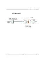
Page 25: ...Introduction and Initial Operation Varian Inc User Manual Micro GC Page 17 Heated Injector Systems...

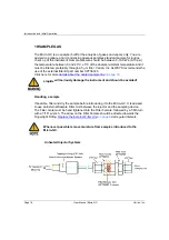
Page 26: ...ensation in the sample lines needs to be prevented The heated sample and injector can be controlled between 30 C and 110 C Connect a heated sample line Before connecting a heated sample line allow the...

Page 27: ...Introduction and Initial Operation Varian Inc User Manual Micro GC Page 19 Insulate the sample line coming into the Micro GC this to prevent damage to the in out coming cables Must be insulated...

Page 28: ...few days please carry out the procedure mentioned below Create a method for all channels with the following settings Filaments switched OFF Column temperature set at 30 C Injector temperature set at 3...

Page 29: ...Connect carrier gas tubing and apply pressure on the Micro GC according the pre installation requirements Wait at least 10 minutes before switching ON the Micro GC Check immediately if the detector fi...

Page 30: ...l Send the instrument parameters from the data handling package software to the Micro GC You can watch the Micro GC status in the instrument status tab INJECTING THE SAMPLE N2 0 77 Nitrogen CH4 89 Met...

Page 31: ...arbon dioxide and ethane are not separated on these columns They produce a composite peak For separation of these components a HayeSep A column is advised Instrument parameters Column temperature 50 C...

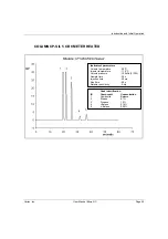
Page 32: ...ED Instrument parameters Column temperature 50 C Injector temperature 110 C Column pressure 150kPa 21PSI Sample time 30s Injection time 40ms Run time 30s Detector sensitivity Auto Peak identification...

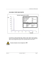
Page 33: ...ED Instrument parameters Column temperature 50 C Injector temperature 110 C Column pressure 150kPa 21PSI Sample time 30s Injection time 40ms Run time 60s Detector sensitivity Auto Peak identification...

Page 34: ...SIL13CB TBM 12 METER HEATED Instrument parameters Column temperature 40 C Injector temperature 50 C Column pressure 250kPa 38PSI Sample time 30s Injection time 255ms Run time 80s Detector sensitivity...

Page 35: ...utes with oxygen Components with a higher molecular weight than propane have long retention times on this column Maximum allowable column temperature 160 C Instrument parameters Column temperature 50...

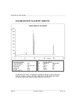
Page 36: ...xygen and some noble gases Higher molecular weight components have much higher retention times on this column Instrument parameters Column temperature 40 C Injector temperature NA Column pressure 200k...

Page 37: ...C max column oven temperature and with the normal operating pressure on the column head leave it to condition for about an hour You are advised to switch the detector filaments off during this period...

Page 38: ...nstrument parameters Column temperature 150 C Injector temperature 110 C Column pressure 150kPa 21PSI Sample time 30s Injection time 40ms Run time 50s Detector sensitivity Auto Peak identification ID...

Page 39: ...ument undergoing internal changes prior to any switching of carrier gas type It is recommended to use gases with a minimum purity of 99 995 Since the injection valve is operated pneumatically there is...

Page 40: ...INJECTOR The injector has a built in 10 l sample loop that is filled with the gaseous sample The pressure of the sample should be between 0 100 kPa 0 15 psi and the sample temperature within 5 40 C 5...

Page 41: ...9 CB Hydrocarbons C4 C10 high boiling solvents BTX CP WAX 52 CB Polar higher boiling solvents PLOT Al2O3 KCl Light hydrocarbons C1 C5 saturated and un saturated Optional Retention Time Stability RTS c...

Page 42: ...the changing thermal conductivity of the carrier gas stream due to components present is compared to the thermal conductivity of a constant reference gas stream DMD The Differential Mobility Detector...

Page 43: ...UTPUTS The Micro GC has several in output ports accessible inside the instrument for interfacing with external devices Open the cover At the front of the Micro GC the external device connectors will b...

Page 44: ...10 11 12 13 14 15 Pin CP 4900 External Ready IN Start IN Micro GC will only start in external ready mode when Start IN detects a contact closure pulse Start 500 ms contact closure when injection will...

Page 45: ...eceived data transmitted data 1 2 3 4 5 6 7 8 9 Pin RXA RS 485 COM 3 RXB TXB TXA COMMUNICATION PORTS COM The instrument can communicates serially with the computer via an RS 232 port COM 1 accessible...

Page 46: ...y the local user interface and or events data to be shown stored in the remote user interface see also External_devices on page 63 Analog GND 1 2 3 4 5 6 7 8 9 10 11 12 13 14 15 Pin 490 GC External An...

Page 47: ...itional sets of RF modulation voltages which results in selective performance which is tuneable depending on the compounds of interest and the matrix Ions generated by a Ni63 radioactive ionization so...

Page 48: ...DMD set up showing different voltages applied As illustrated in Figure 1 the net voltage applied results from three independent settings 1 A fixed voltage or RF Voltage 2 A scanning voltage also refe...

Page 49: ...etting compensation voltages to accommodate transmission of the compound of interest in that particular part of the chromatogram This time segmented detection thus leads to maximum selectivity for the...

Page 50: ...rkstation package the DMD will be handled as a separate channel With respect to the operation of the DMD note the following In instrument configuration selection of carrier gas type and heated injecto...

Page 51: ...ing computers to share resources across a network TCP and IP are the two best known protocols in the Internet Protocol Suite Other protocols services are FTP Remote Login Telnet Mail SMTP IP Addresses...

Page 52: ...n IP Address A No The GC works with static IP addresses only so an IP address will have to be reserved on the DHCP server and marked as static Q How do I assign the GC with an IP address A Connect the...

Page 53: ...used to establish connections with Ethernet devices The Gateway is assigned an IP Address Host name The host name is an alternate way of identifying a device that is friendlier to people Frequently th...

Page 54: ...ephone jack style connector used for a Universal Twisted Pair UTP hardware connection for 10 100BaseT Ethernet connections RJ45 style connectors are used by the Micro GC TCP IP An international standa...

Page 55: ...rnet only IP Settings BootP RS232 BootP RS232 Com 1 RS232 Not available Com 2 Stream selection on Com 2 Stream selection on Com 2 Com 3 Not available Not available Analog I O Capturing Yes via Analog...

Page 56: ...is limited by your license The 490 GC driver scope CONTROL INSTRUMENT Ethernet control on page 50 TCP IP is standard Even if the instrument is equipped with Ethernet it is possible to control the inst...

Page 57: ...nication problems due to high communication speed baud rate 115200 bits sec The maximum number of Micro GCs controlled by serial communication is two Choose Ethernet communication in case more than tw...

Page 58: ...ent must be different In case both the computer as well as the Micro GC are connected to a local network this cable cannot be used for control of the Micro GC However this crossover cable must be used...

Page 59: ...ocal network EZChrom Elite maximum connections are limited by the computer speed license and network performance Switch Patch Cable Workstation Any IP address allowed 490 GC Multiple 490 GCs connected...

Page 60: ...net 2 EZChrom Elite IP address in range of subnet 1 490 GC Multiple 490 GCs connected to a companies network IP address in same range of subnet 1 Switch Router Internet EZChrom Elite IP address in ran...

Page 61: ...e instrument via RS485 Com1 on the Micro GC is fixed configured as RS232 The baud rate is fixed at 115200 bit sec Ethernet communication Galaxie For Ethernet communication select Configure system foll...

Page 62: ...teway IP address if this is required In most small local network this is not required 6 Enter the Domain if this is required In most local network this is not required 7 Enter a Host name for the Micr...

Page 63: ...that must be assigned to the Micro GC This IP address must be in the same range as the computers IP address The three left IP segments must be identical 5 Enter the Subnet Mask This will be in most c...

Page 64: ...Serial number Channel 1 Controller 1202 Serial number Channel 2 Controller 1203 Serial number Channel 3 Controller 1204 Serial number Channel 4 Controller 1205 Serial number Channel 1 Analytical Modu...

Page 65: ...External Analog Input 2 at start of run copied from address 1232 1239 External Analog Input 3 at start of run copied from address 1233 1240 External Analog Input 4 at start of run copied from address...

Page 66: ...event 2 Pressure restored 3 Start flush cycle 4 Flush cycle passed 5 TCD calibrating 6 Too low pressure 7 Pressure fault 8 Low battery 1 9 Low battery 2 10 Sample line sensor fault 11 Sample line tem...

Page 67: ...rrect 46 EDS C C Config SVER incorrect 47 EDS C C Protected SVER incorrect 48 EDS A M Config SVER incorrect 49 EDS A M Protected SVER incorrect 50 Pressure Offset calibration complete 51 Pressure Offs...

Page 68: ...be setup out of almost any parameter available in all application part of this schedule Everything stored in the shared UserDataStore database can be used to setup a switch condition since every Vari...

Page 69: ...ument maximal four instruments ISOCAL32 BTU32 ValveControl32 Address Parameter Address Parameter Address Parameter 0 Calib Level 200 Calib Level 402 Current Stream Position 1 Total ESTD 201 Total ESTD...

Page 70: ...ter 501 Calib Level and SampleID 511 Stream Position from CP Maitre Elite 512 Total ESTD summed of all channels EliteExport dll or Mlink32 520 and up User defined parameters as defined in the UserData...

Page 71: ...supports the start of the Micro GC by an external device Flow computer or PLC The Micro GC processes this event start run and passes the event to the driver see also External_digital_IO on page 36 4 E...

Page 72: ...Reference Page 64 User Manual Micro GC Varian Inc...

Page 73: ...ith static electronic pressure This time diagram will help you to understand the Static electronic pressure cycle of the Micro GC The run can be started when the is ready Ready LED is lit The Workstat...

Page 74: ...essure control EGC cycle of the Micro GC The diagram shows the situation in the Micro GC using electronic programmed pressure control The timing before the injection is identical to the static pressur...

Page 75: ...GC module has been stored for a long period The detector filaments may be damaged if this procedure is not followed 1 Switch off the TCD filaments in the method 2 Set the column temperature of the mod...

Page 76: ...analysis time The Varian Micro GC is optionally available with GC modules that incorporate backflush capabilities A backflush system always consists of a pre column and an analytical column The two co...

Page 77: ...the backflush valve switch at the backflush Time On the pre column the flow is inverted and all compounds left on the pre column are now back flushed to the vent see backflush diagram On the analytic...

Page 78: ...mn How to Tune Obtain a chromatogram in foreflush Check out the retention times of the compounds you have to quantify Start at a backflush time of 10 seconds Obtain a second chromatogram Adjust the Ba...

Page 79: ...t protection plugs on the sample and carrier gas inlets Put protection plugs on the Column vents Use a soft no hard or abrasive brush to carefully brush away all dust and dirt If the outer case is dir...

Page 80: ...error messages indicate certain malfunctions of the instrument Some errors of this type keep the instrument from becoming ready Class 2 Critical errors for logging error LED ON These are critical err...

Page 81: ...e line temperature sensor error Heater turned off 2 11 Sample line temperature fault Temperature not reached within 35 min heater error Replace sample line heater 2 12 Injector temperature fault Tempe...

Page 82: ...ncorrect NA 0 44 EDS Config SVER incorrect Electronic Data Sheet Configuration Structure Version incorrect NA 0 45 EDS Protected SVER incorrect Electronic Data Sheet Protected Structure Version incorr...

Page 83: ...error Internal communication error Reboot 2 75 DMD sensor error Startup sensor diagnostic fail Call service 3 76 IOC Communication error MPU is not able to communicate with IOC Call service 3 77 Read...

Reviews: