ProStar325 Service Manual
Publication date 8 May 2003
53
3.11
Instrument
setup
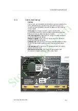
Cabling
The monitor, printer/plotter and detector are all connected to the
PC by cables that plug into the back of the PC. Consult your
monitor and printer/plotter manuals for details of their cabling
requirements.
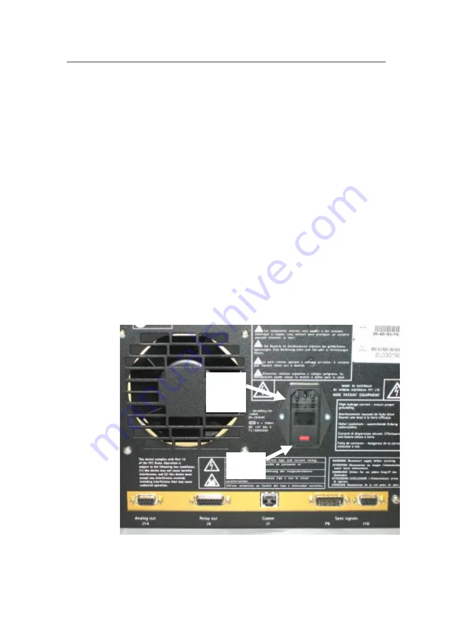
J1 Comm:
RJ-45 type connector used to interface the
ProStar325 to the PC by using a 100ohm shielded twisted pair
Ethernet crossover cable Category 5 or better.
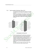
J10 Sync signals:
female 9-pin “D” range connector used with
synchronization signal cables.
P9 Sync signals:
male 15-pin “D” range connector used with
synchronization signal cables.
J4 Relay out:
female
15-pin “D” range connector used to control
the four programmable external event relays and peak sense
relay.
J14 Analog out:
female 9-pin “D” range connector for Analog
output channels A & B.
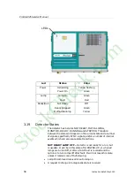
Electrical connection:
the universal mains power inlet
connection is located at the rear of the instrument.
Mains
power
inlet
Fuse
holde
r
StockCheck.com
Summary of Contents for ProStar 325 UV-Vis
Page 9: ...ProStar325 Service Manual Publication date 8 May 2003 9 S t o c k C h e c k c o m ...
Page 19: ...ProStar325 Service Manual Publication date 8 May 2003 19 S t o c k C h e c k c o m ...
Page 34: ...ProStar325 Service Manual 34 Publication date 8 May 2003 S t o c k C h e c k c o m ...
Page 71: ...ProStar325 Service Manual Publication date 8 May 2003 71 S t o c k C h e c k c o m ...
Page 72: ...ProStar325 Service Manual 72 Publication date 8 May 2003 S t o c k C h e c k c o m ...
Page 118: ...ProStar325 Service Manual 118 Publication date 8 May 2003 S t o c k C h e c k c o m ...
Page 149: ...ProStar325 Service Manual Publication date 8 May 2003 149 S t o c k C h e c k c o m ...


