I
NSTALLATION
ProStar 335 Photodiode Array Detector
51
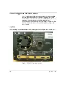
The following table summarizes the function of each connection:
Table 1 Rear panel services functions
Service Function
Main power receptacle
3-pin receptacle with 2 fuses
J14 Analog out
9-pin female ‘D’ shell connector used for two channels (A and
B) of analog output
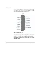
J4 Relay out
15-pin female ‘D’ shell connector used for time programmed
contact closures
J1 Comm
RJ-45 type connector used to interface the ProStar 335
detector to a desktop PC or network
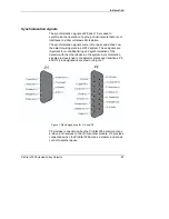
P9 Sync signal
15-pin male ‘D’ shell connector used with synchronization
signal cable
J10 Sync signal
9-pin female ‘D’ shell connector used with synchronization
signal cable
AC power
The ProStar 335 detector may be connected to any voltage in the
range 100–240 VAC ± 10%, 50/60 Hz ± 1 Hz, without
modification or the need to change fuses.
All power supplies must be single-phase AC voltage, three-wire
system (active, neutral, earth) and should be terminated at an
appropriate power outlet receptacle that is within reach of the
detector power cord assembly.
All ProStar 335 detectors are supplied with a 2 metre (6' 6") long
power cord and three-pin plug assembly that is compatible with
common standards applicable in the local area.
Avoid using power supplies from a source that may be subject to
electrical or RF interference from other services (large electric
motors, elevators, and welders for example).

