I
NSTALLATION
ProStar 335 Photodiode Array Detector
73
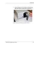
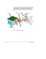
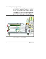
To remove a flowcell, follow the above steps in the reverse order.
NOTE:
The flowcell should be removed with the connecting tubing fitted. These
must be removed outside the detector compartment.
If you change the type of flowcell, a lamp calibration should be
performed (refer to page 100).
Detector outlet back pressure restrictor
If you are using a 9 x 0 or 4 x 0 flowcell, or a 9 x 1 flowcell at
lower flow rates for microbore to analytical work, the back
pressure restrictor assembly (part number 01-107433-00) that
was supplied with your detector should be threaded into the
outlet line from the flowcell. The back pressure restrictor provides
approximately
40 psi back pressure on the flowcell. This prevents outgassing
and bubbles which can cause an unstable baseline from forming
or being trapped in the flowcell.
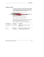
Note that the arrow stamped on the restrictor body must point
away from the flowcell outlet port, and toward the waste receiver.
The threaded plastic fittings should be finger-tightened only
enough to prevent leaks.
About 122 cm (48") of 1.6 mm (1/16") tubing is supplied at both
the inlet and outlet of the restrictor. The inlet tubing is provided
with a 1.6 mm (1/16") plastic tubing fitting for connecting to the
flowcell outlet port. Either the outlet tubing can be directed to the
waste container, or the tubing removed, and the restrictor itself
dropped to the bottom of the waste bottle.
The restrictor pressure setting is not adjustable. If the restrictor
fails or becomes plugged, replace the existing cartridge with a
new 40 psi replacement supplied in the Cartridge Replacement
Kit (part number 03-919239-90). Restrictors with higher back
pressures are available if the mobile phase you are using causes
significant bubble problems with the standard restrictor.

