68
03-914875-00:1
Assembly of Flow Cell
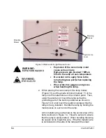
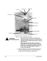
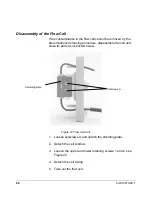
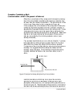
1. Assemble the flow cell into the cell holder in the orientation
shown in Figure 23 and fix it with the cell clamp.
2. Tighten the upper and lower retaining screws.
Figure 23 Assembly of Flow Cell Unit
3. Attach the cell window and shielding plate.
4. After assembling the flow cell in the order reverse to
disassembly, flow a liquid through the unit and make sure
there is no leakage.
NOTE 1:
During assembly be careful not to scratch the flow cell
surface.
NOTE 2:
Be sure you properly position the flow cell when putting
it into the cell holder. (See Figure 23.) A mistake in the
orientation may preclude obtaining the proper
performance from the instrument.
NOTE 3:
Finger-tighten retaining screws 1 and 2 fully, then
tighten another 1/3 turn or so with an open–end wrench.
(instrument
front)
Flow Cell
Transmitted
excitation light
(instrument rear)
Emission
Excitation
light
Polished Surfaces
Enlarged view of flow cell
(Top View)
Summary of Contents for ProStar 363
Page 2: ......
Page 6: ...iv 03 914875 00 1...
Page 20: ...14 03 914875 00 1...
Page 82: ...76 03 914875 00 1...

