2.1 CP/MAS Solids Modules
01-999162-00 C0402
VNMR 6.1C User Guide: Solid-State NMR
18
• Enable high power amplifier operation
Place the
LO BAND
amplifier switch in the
HI POWER
position (an orange LED will
illuminate) and enable high power with the silver button.
• Disable the high power amplifier operation
Place
LO BAND
amplifier switch in the
LO POWER
position and press the red button.
If a 300 W lowband amplifier is present in the console it will now be enabled.
Low-band amplifiers operate in either pulsed or CW mode. The operation mode is
controlled by the
ampmode
parameter. When the parameter
ampmode
is not present the
amplifier is set in the default (CW) mode (
ampmode
=
‘c’
or
‘d’
) which is correct for
CP/MAS experiments.
Fine Attenuators
UNITY
INOVA and UNITYplus Systems
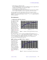
The standard
UNITY
INOVA
and UNITYplus system
transmitter board
provides fine power
control over a range of 0
to 60 dB in 4095 steps.
Output in voltage or field
strength is linear and
quadratic in power. The
attenuator control in dB
is shown in
. A
rough rule is; for a 2 fold
change in fine power
there is a 6 db change in
the coarse power (
tpwr
or
dpwr
). Power is controlled using the parameters:
tpwrf
,
dpwrf
,
dpwrf2
, and
dpwrf3
. Aliases of these parameters ending in
m
rather than
f
are
used in some pulse sequences, including XPOLAR1. The parameters
crossp
and
dipolr
in XPOLAR1 are two different values that set
dpwrf
during the cross
polarization and decoupling periods respectively.
MERCURYplus and MERCURY-Vx Systems
The transmitter board
provides fine power
control over a range of
0 up to 40 db in 255
amplitude steps using
the parameters
tpwrf
and
dpwrf
. Output in
voltage or field strength
is linear and quadratic in
power. The attenuator
control in dB is shown in
36
42
48
54
60
30
35
40
45
50
55
60
65
0
1000
2000
3000
4000
Attenuator Value
dB
Figure 1. Attenuator Control Graph for INOVA Systems
24
30
36
42
48
20
25
30
35
40
45
50
0
50
100
150
200
250
300
Attenuator Value
dB
Figure 2. Attenuator Control Graph for Mercury Systems


