5.2 Rotor Synchronization Operation
01-999162-00 C0402
VNMR 6.1C User Guide: Solid-State NMR
74
For light detection, the tachometer box provides the
light source and the detector. The rotor has a blackened
sector on its base (
) so that as it rotates,
differing amounts of light are reflected. The light is
transferred through light pipe to the stator base. The
reflected light is sampled by another light pipe and
brought back to the tachometer box where it is
photodetected. The resulting current is amplified and
used to toggle a Schmitt trigger that is the input to the
external time base of the Acquisition Controller or
Pulse Sequence Controller board.
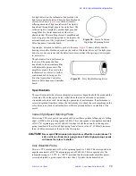
In principle, detection in the Doty probe is the same.
shows a Doty double-
bearing rotor with a blackened sector on the inside of the lower drive cap. The light pipes,
however, are not as precise and the detection is more indirect, thus giving a lower signal-
to-noise ratio.
The photodetection is performed in
the base of the probe and then
transferred to an external amplifier
with adjustable gain control. The
amplifier output is then sent to the
tachometer box where it is further
conditioned before being used to
drive the Acquisition Controller
board or Pulse Sequence Controller
board.
Specifications
The specifications for the rotor synchronization accessory depend on both the probe and the
electronics. The values given below reflect those that can be obtained in optimum
circumstances and, as such, do not imply a guarantee of performance. If performance is
severely degraded from these values, the first remedy is to check the sector markings on the
rotor, because any lack of definition here will have profound effects on stability of the
result.
Varian High-Speed Spinning Probe
Jitter in one TTL rotor period (measured with an oscilloscope from falling edge to falling
edge) is
≤
500 ns for spinning speeds to 8 kHz. This corresponds to an angular uncertainty
of
≤
0.5
°
at a spinning speed of 3600 Hz. An edge is detected normally as the negative-
going transition of the reflected light going from at least a value of –39 dBm to no more
than –45 dBm, measured at the end of the fiber optics.
CAUTION:
Never spin PSZ (zirconia) rotors (white or off white in color) above 7.5
kHz or silicon nitride rotors (gray) above 9 kHz. High spinning speeds
will cause the rotors to shatter.
Doty Scientific Probe
Jitter in a TTL rotor period is
≤
2
µ
s for spinning speeds to 5 kHz. This corresponds to an
angular uncertainty of
≤
2
°
at a spinning speed of 3600 Hz. This is expected over the
temperature range of –50
°
C to +100
°
C, provided that the tachometer amplifier gain is
correctly adjusted to give a signal of no less than 1 Vpp into the tachometer box.
Figure 28. Base of a Varian
High-Speed Spinning Rotor
Figure 29. Doty Double Bearing Rotor


