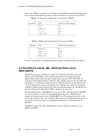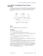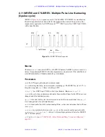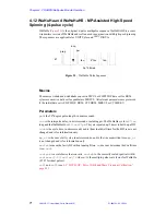
4.2 CRAMPS/Multipulse Module Hardware
01-999162-00 C0402
VNMR 6.1C User Guide: Solid-State NMR
58
c.
After tuning at lower power, fine tune at the maximum power that will be
used in order to obtain the maximum linearity of the CPI or the CMA.
d.
Record the values for future reference.
Overdrive Mode
The CPI amplifier contains an
OVERDRIVE
RESET
button on the front panel. An overdrive
state is indicated by the lighted red word on the relay panel at the top of the solids bay. Press
to reset when the word is lighted. The CMA amplifier contains a
TRIP
RST
button and an
overdrive state is indicated by a red light on the front of the chassis. In overdrive mode the
amplifier is shut down. An overdrive fault is caused by excessive power or an arc in the
probe, and sometimes by pulsing into a mismatched cable. The overdrive usually must be
reset when the acquisition computer is restarted.
Amplifier and Receiver Blanking
The BR24 pulse sequence for CRAMPS, makes use of amplifier blanking to remove
amplifier noise during the acquisition of data points between the pulses. Set the parameter
ampmode = p
or
d
for pulsed mode. The parameter
ampmode
is also set correctly if the
parameter is not present. The newer CMA amplifiers should be run with the toggle in the
GATE
ACTIVE
(pulsed) position. Older CPI amplifiers are automatically set to pulsed mode
using the value of the
ampmode
parameter.
In pulsed mode the CPI and CMA amplifiers are turned on at the beginning of the period
rof1
before the pulse. They are ready for full RF output after
rof1=1.5
to
2.0
µ
s
. The
minimum value of
rof1
=
1.5
µ
s
is used for CRAMPS. The amplifiers are turned off after
a period
rof2=0.2
to
0.5
µ
s
after the pulse. For
1
H CRAMPS the noise and RF “ring
down” over a period of about 2.0-3.0
µ
s before detection of a data point is possible. During
this period the T/R switch (if present - see Solids Preamplifiers below) immediately gates
to receive mode and then after a delay a trigger is sent to turn the receiver on. When using
the fast ADC the receiver then turns on within about 1.0
µ
s
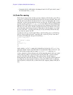
The delay between triggering the T/R switch and the receiver is set by a hardware
adjustment on the magnet leg. The default value is about 2.0 microseconds for a highband
nucleus and about 8.0 microseconds for a lowband nucleus. The purpose is to protect the
receiver (outside of pulse-sequence control) from pulse ring down that will “certainly” be
present. If one collects a data point before the receiver turns on by setting tau too short in
BR24 or FLIPFOP, the result will be a null signal. In this case lengthen
tau
. The hardware
delay is accessible to users and can be made shorter if desired to allow smaller values of
tau
.
Optionally, a CMA amplifier may be set in CLASS C (nonlinear) mode. In this case the RF
pulse of the 50-Watt driver amplifier turns the CMA on and off. Blanking instructions of
the pulse sequence are ignored. Set
ampmode='c'
to operate the 50 watt driver in
continuous mode. CLASS C mode provides a slightly shorter unblanking time (
rof1
) but
RF output in CLASS C mode is not linear. It will be necessary to retune and recalibrate the
parameters
tpwr
and
tpwrf
or
tpwrm
when using CLASS C mode.
FAST ADC (2 MHz or 5 MHz)
The CRAMPS experiment requires an optional fast ADC, which may be either 2 MHz or 5
MHz. This device sits in the acquisition card cage and is connected to the receiver ports WB
CH A and WB CH B (J246 and J247) with a pair of BNC cables. These ports provide the
real and imaginary FID signals and bypass the analog filters. The unfiltered FID signal from

