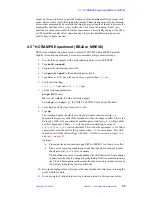
4.4 Multipulse Tune-Up Procedure (FLIPFLOP)
01-999162-00 C0402
VNMR 6.1C User Guide: Solid-State NMR
62
• Optionally
a.
Type
phaser=phfid
,
phfid='n'
b.
Reacquire the spectrum.
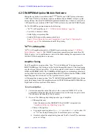
This will adjust the pulse phase to place the signal in one of the two ADC
channels. Otherwise, it usually sufficient to observe a phased display. The
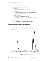
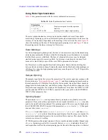
real channel should appear similar to
. or
4.
Type
gf
and then
acqi
.
5.
Press the FID button and then press again to select the FID display.
6.
Press IPA and adjust the
tpwrf
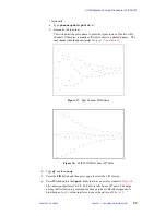
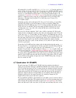
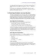
slider to achieve a display similar to
The ideal signal pattern (1.0,0.0,-1.0,0.0)N results from a 90
o
pulse. The bulge
among the first few zero-points and the decay are due to RF inhomogeneity. A
distribution of
pw90
values interferes to cause the pattern of
.
Figure 17. Real Channel FID Pattern
Figure 18. FLIPFLIP FID at Exact 90
°
Pulse


