

1-1
SECTION I
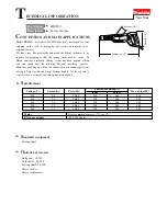
INSTALLATION
Before unpacking and installing the VHS-6 Diffusion Pump, the user should thoroughly familiarize
himself with this instruction manual and the diffusion pump specifications (see Table 1). He should
also examine all other technical material supplied in order to gain a better understanding of the oper-
ating principles, limitations, correct application, and the hazards involved with the use of this equip-
ment.
1-1
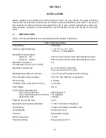
SPECIFICATIONS
Table 1 lists the specifications for all standard type 0184 models of the pump.
Table 1. Pump Specifications
Power Rating
2200 watts
Optimum Operating Range
1 x 10
-3
to < 5 x 10
-9
(Torr)
.133 Pa to < .000000665 Pa
Maximum Pumping Speed
(liters/sec – air)
2400 with std cold cap; 1600 with extended cold cap
(liters/sec – helium)
3000 with std cold cap; 2000 with extended cold cap
Maximum Throughput
3.5
(Torr liters/sec at 0.01 Torr (13.3 Pa))
Maximum Forepressure
No Load: 0.65 Torr (86.45 Pa)
Full Load: 0.55 Torr (73.15 Pa)
Backstreaming Rate at Pump Inlet
<5 x 10
-4
mg/cm
2
/minute (with std cold cap)
Power Required (approximately)
120, 240, 208, 50/60 Hz, single phase
Warmup Time
9 minutes
Cooldown Time (using quick cool coil)
10 minutes
Fluid Charge
500 cc
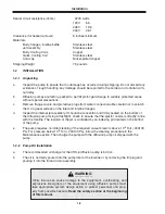
Cooling Water Requirements
(max. inlet temperature)
60/80 degrees F
(max. outlet temperature at foreline)
120 degrees F
(general flow rate)
0.25 gpm
Pressure drop across coils
15 psi
Backing Pump Size Recommended
17 cfm for maximum throughput
Jet Assembly
4-stage, self-aligning, stainless steel
Foreline Baffle
Stacked half moon
Cold Cap
Nickel-plated Copper
Water Connections
1
⁄
8
FPT
Thermal Switches
Manual reset at 300°F
Summary of Contents for VHS-6
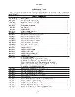
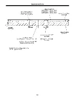
Page 27: ...Replacement Parts 5 2 ...
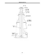
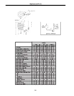
Page 28: ...Replacement Parts 5 3 ...