Maintenance and Service
c
Unbolt the inlet flange and foreline connections. Remove the pump from the system.
d
Drain the diffusion pump of all fluid.
e
Remove all O-rings, the cold cap assembly, the jet assembly, and the foreline baffle from the
pump.
f
Thoroughly clean the diffusion pump body interior and the jet assembly using acetone
followed by an isopropyl alcohol rinse. Dry the pump and the jet assembly with clean,
dry, oil-free compressed air.
g
Install the foreline baffle, the jet assembly, and the cold cap assembly in the pump body.
Check that the ejector nozzle is properly aligned with the foreline. Also check that the cold cap
is properly installed on the jet assembly. The space between the underside of the cold cap
and the outside of the jet cap should be uniform.
h
Reinstall the diffusion pump in the system using all new O-rings.
i
Charge the pump with the proper amount of fluid.
j
Reconnect the water cooling lines and the power supply.
k
Evacuate the diffusion pump with the appropriate mechanical pump.
l
Turn on the cooling water.
m
After the pump has been evacuated to a pressure below 0.5 Torr (66.5 Pa), turn on the
power to the diffusion pump.
3-4
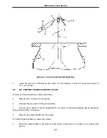
COLD CAP REMOVAL/INSTALLATION (Refer to Figure 3-1)
To remove the cold cap, proceed as follows.
a
Remove the spring (1) attached by no. 6-32 x
3
⁄
16
round head screw (2), a flat washer (3), and
a lockwasher (4).
b
Loosen the nut (5) holding the cold cap bracket (6) to the copper bar (A) and remove the
cold cap (7) from the top of the jet cap (8).
c
Unscrew the no. 8-32 x
1
⁄
4
socket head cap screw (9) from the top of the ceramic standoff (10).
d
Remove the ceramic standoff (10) and the no. 8-32 x
1
⁄
2
stud (11).
To install the cold cap, proceed as follows.
a
Replace the stud (11) and the ceramic standoff (10) in the jet cap (8).
b
Thread the no. 8-32 x
1
⁄
4
socket head cap screw (9) finger-tight into the top of the ceramic
standoff (10). Be careful not to crack the ceramic standoff.
c
Carefully place the cold cap (7) on top of the jet cap (8), align the cold cap bracket (6)
with the copper bar (A), and level the cold cap as accurately as possible.
d
Tighten the nut (5) at the copper bar (A).
3-2
NOTE
________
In the following step, be sure that no strain is applied to the ceramic
standoff when tightening the nut (5) at the copper bar (A).
Summary of Contents for VHS-6
Page 27: ...Replacement Parts 5 2 ...
Page 28: ...Replacement Parts 5 3 ...

