background image

25

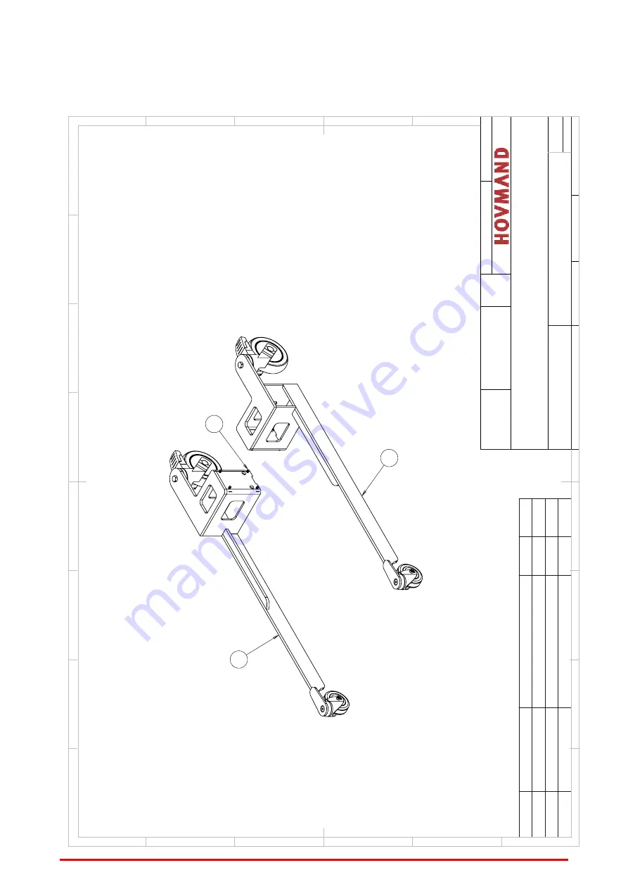
15.7 leg set

1

2

3

ITEM NO.

PART NUMBER

DESCRIPTION

QTY.

revision

1

30016226

Legset-box-650 right SS complete

1

1

2

30016231

Legset-box-650 left SS complete

1

1

3

81010395

Screw M6x12 CH A2 DIN 912

8

-

D

E

F

C

1

2

3

4

B

A

3

2

1

5

C

D

4

6

7

8

A

B

Date[yy.mm.dd]:

20.06.10 

INOX 90

UNLESS OTHERWISE SPECIFIED: DIMENSIONS ARE IN MILLIMETERS AND WITH TOLERENCES AFTER DS/ISO 2768-1 MIDDEL

FINISH:

DEBUR AND  BREAK SHARP  EDGES

DO NOT SCALE DRAWING

TITLE:

DWG NO.

1:5

SHEET 1 OF 1

WEIGHT: 12.88 Kg

DRAWN BY: RBK    

30016234

30016234

Leg-Box-650x465-75s

Revision:   1

MATERIAL:

A3

Summary of Contents for Flexlift INOX mini

Page 1: ... MANUAL SERIAL NUMBER ____________________ Varimixer A S Kirkebjerg Søpark 6 DK 2605 Brøndby Denmark P 45 4344 2288 E info varimixer com www varimixer com SAP nr 20060 1710 Version 1 1 UK Original language English ...

Page 2: ... the Machinery Directive 2006 42 EC Annex II A The following directives and standards as well as technical reports have been applied insofar as they have been found to be wholly or partly relevant in relation to the construction and design of the machine Directives 2014 30 EC 2014 35 EC 2011 65 EC Standards EN ISO12100 2011 EN ISO TR 14121 2 2012 EN 60204 1 2016 EN IEC 63000 2018 EN ISO3691 5 2015...

Page 3: ... The following directives and standards as well as technical reports have been applied insofar as they have been found to be wholly or partly relevant in relation to the construction and design of the machine Directives Electromagnetic Compatibility Regulations 2016 Electrical Equipment Safety Regulations 2016 RoHS Regulations 2012 GB Standards BS EN ISO12100 2011 ISO TR 14121 2 2012 BS EN 60204 1...

Page 4: ...ifting equipment 13 9 1 Quick Clamp with turning unit QC3 13 9 2 Light Indicator 14 9 3 Adjustments 14 9 4 Adjusting speed and Amps for gripping unit 14 10 Maintenance and Inspection 15 11 Disposal 15 12 Cleaning instructions 16 13 Resolving faults 17 14 Electrical chart 18 15 Spare parts 19 15 1 Flexlift INOX mini Complete 19 15 2 Mast Complete 20 15 3 Mast 21 15 4 Control box 22 15 5 Turning uni...

Page 5: ...our fingers crushed Warning This pictogram draws attention to the risk of personal injury l The lifter must not be used for lifting persons Warning This pictogram draws attention to the risk of personal injury l There should be no body parts below or near the lifting tool when operated up or down Warning This pictogram draws attention to the risk of personal injury l There should be no body parts ...

Page 6: ... kg 83 Height mm 1524 Max load kg 50kg Lifting speed normal speed 100 125 mm s Protection class IP66 Batteries 24V 18AH Charger 90 264V 47 63Hz 2 5 Amps Charging time 6 hours 80 8 hours 100 Sound pressure level 70 Db A Vibration strength 2 5 m s ...

Page 7: ...lift when operated on a hard levelled surface during lifting or transporting loads l When transporting a cargo the load should be lowered to the lowest possible position and secured in order to ensure that the cargo cannot slide l Always secure the cargo on the lift when moving l Not in use or storing always ensure that the sledge is lowered to the lowest possible pos ition and is free of any item...

Page 8: ... for extraordinary wear material or product failure due to great impact from col lision misuse obstacle interference blockade of driveways etc e g a faulty wheel bearing as a result of a heavy collision Residual risk for personnel working with or around the lifter A Do not use the lifter or tool with unstable unbalanced load B No persons or body parts must be put under or near the tool C Do not pu...

Page 9: ...wering The lifter will lower while the button is pressed Normal speed 3 Turning left counter clockwise 4 Turning right clockwise 5 6 Manipulator reduces grips 2 buttons must be pressed at the same time 1 7 8 Manipulator expands eases grip ping 2 buttons must be pressed at the same time 2 6 2 Shipping When shipping the lifter l The sledge must be lowered to the lowest possible position and be free ...

Page 10: ...nel before lifting lowering rotating or using the tool When lifting lowering rotating or using the tool the operator must stand behind the wheels of the lifter as illustrated below n A ensure that all other personnel are out of the danger zone as illustrated below n B n Lifter n Tool n Safety area for operator A Safety distance 1500 mm n Safety area for other personnel B safety distance 3000 mm ...

Page 11: ...el 1 4301 AISI 304 Handle Electro polished stainless steel 1 4301 AISI 304 Sledge Electro polished stainless steel 1 4301 AISI 304 Front cover for mast Electro polished stainless steel 1 4301 AISI 304 Remote Polyamide 6 Wheel frame Electro polished stainless steel 1 4301 AISI 304 Front wheels Polyurethane Back wheels Polyamide and Polyurethane ...

Page 12: ... 8 hours The charger automatically charges the batteries and switches to maintenance char ging when the batteries are fully charged Safety when charging Use only original charger Check that the wires are in good condition connect properly and cor rect before applying power Make sure there are no dirt or water in the plug The battery status indicator The lifter is equipped with a battery status ind...

Page 13: ... suitable for handling the specific item Do not handle items which you have not specifically made adjustments for or settings to suit Before the turning unit is activated control that the load is correctly held between the arms of the tool This is done by ensuring that all contact areas of the tool are indeed in contact with the load Make sure that the load is lifted high enough so that no collisi...

Page 14: ...ettings to suit the item that is handled The rotational speed can be adjusted in the PLC settings 9 4 Adjusting speed and Amps for gripping unit Parameters should only be adjusted by skilled technicians as improper procedures may lead to insufficient clamping power and or irreversible motor damage The following parameters may be adjusted in the control box P3 Used for adjusting amps on gripping cl...

Page 15: ...intervals stated to make sure that the lifter is in safe operational condition Critical components Please contact Hovmand for instruction on how to replace critical components Cam belt l Replace when if any of the below points occur l Any sign of wear visual cracks or miscolour l Under normal use Use 20 lifts per day in average over a year replace after 8 years l Under intensive use Use 20 lifts p...

Page 16: ...t you don t risk a head injury when cleaning near the floor Detergent application Use a standard PH neutral cleaning detergent Do not use Acid Alkaline or harsh chemical products these might weaken the drive belt and other sensitive components or leave marks on the surfaces Work process l The outer surfaces can be cleaned using a wet brush or a damp cloth l The outer surfaces can be cleaned using ...

Page 17: ... the sledge runs Remove the dirt and wipe with alcohol Is there dirt on the sledge wheels Remove the dirt or replace the wheels The lifter does not respond Check whether the item being lifted is heavier than the lift s capacity Remove the item Check the main fuse or the on off button Replace the main fuse or press the but ton Check that the batteries are charged Connect the charger The lift works ...

Page 18: ...18 14 Electrical chart ...

Page 19: ...pact 130 3L M 1 7 84290031 Remote control INOX 200 3 function 1 8 30010004 Charger 100 240VAC 24V 1 8A INOX 1 9 30017457 QuickClamp 30 60L 1 10 81010194 Screw M6x16 CS A2 DIN 7991 8 11 81030025 Washer M8 A2 DIN 125 A 4 12 81010233 Screw M8x20 CH A2 DIN 912 4 13 81010315 Screw M4x10 BH A2 ISO 7380 2 14 81010343 Screw M3x6 BH A2 ISO 7380 4 MATERIAL Revision 2 INOX 90 3L Box 650 75ds QC3 Kitchen 6101...

Page 20: ...te plug 1 10 30006516 Control box cover INOX 200 1 11 81010466 Screw M5x6 BH A2 ISO 7380 12 12 81010455 Screw M4x8 CH A4 DIN 912 4 13 84020072 Mascot Charger 1 REVISIONS ZONE REV DESCRIPTION DATE APPROVED See Sheet1 A B C D E F G H 1 2 3 4 5 6 7 8 A B C D E F G 1 2 3 4 5 A2 MATERIAL Revision 2 Mast INOX 90 3L complete 40010494 40010494 DRAWN BY LL WEIGHT 46 93 Kg EP SS SHEET 2 OF 2 1 10 DWG NO TIT...

Page 21: ...200 2 17 30008073 Motor Inclosure INOX 90 1 18 30012918 Cover plate for INOX 90 3 1 19 84281769 Wiring for topstop INOX 90L 1 20 40003965 Cover plate INOX 90L 1 21 81010274 Screw M8x10 BH A2 ISO 7380 4 22 81010203 Screw M8x16 CS A2 DIN 7991 1 23 40002247 Parallel key A5 x 5 x 25 DIN 6885 1 24 81100012 Circlip 25x1 2 A2 DIN 471 1 25 81010452 Hex screw M6x60 A2 ISO 4017 2 26 81010453 Screw M3x14 CH ...

Page 22: ...int connect 6 polet 3 18 2010198 PCB connection plug 3 poles angled 3 19 84170070 Trimmer 10K 3 20 84170069 Condensator x2 0 47uf 275V 2 21 84050035 Fuse Auto 30A 1 22 84070047 2 Cap for 84070047 1 23 84281762 Wire set INOX basis 1 24 84281763 Wire set INOX suppl 3 exit 1 25 84281764 Wire set INOX 4 batterier 1 26 81020069 Flange nut M3 FZB DIN 6923 18 27 81010383 Screw M3x10 CH FZB DIN 912 2 28 8...

Page 23: ...20 CS A2 DIN 7991 11 19 81010224 Screw M6x20 CH A2 DIN 912 4 20 81010504 Pinol screw 8x20 A2 DIN 915 1 21 81010194 Screw M6x16 CS A2 DIN 7991 4 22 81030041 Washer M6 A2 DIN 9021 2 23 81010330 Skrue 6x16 CH A2 DIN 912 2 24 81030023 Washer M5 A2 DIN 125 A 1 25 81010492 Screw M3x5 CS A2 DIN 7991 1 26 81030024 Washer M6 A2 DIN 125 A 2 27 81010364 Screw M6x10 CH A2 DIN 912 2 28 81010421 Screw M3x5 CH F...

Page 24: ...2 ISO 7380 4 12 81010266 Screw M6x16 BH A2 ISO 7380 4 13 30001651 Cover for actuator QuickClamp 1 14 81010271 Screw M6x40 BH A2 ISO 7380 4 15 81010175 Bolt for actuator M10x40 afkortet 2 16 81020050 Låsemøtrik M10 A2 DIN 985 2 17 40000671 Bracket for actuator 2 18 81010193 Screw M6x12 CS A2 DIN 7991 4 19 40001053 Dupsko 80x40 1 20 81020048 Lock nut M6 A2 DIN 985 4 21 81010230 Screw M6x50 CH A2 DIN...

Page 25: ...w M6x12 CH A2 DIN 912 8 D E F C 1 2 3 4 B A 3 2 1 5 C D 4 6 7 8 A B Date yy mm dd 20 06 10 INOX 90 UNLESS OTHERWISE SPECIFIED DIMENSIONS ARE IN MILLIMETERS AND WITH TOLERENCES AFTER DS ISO 2768 1 MIDDEL FINISH DEBUR AND BREAK SHARP EDGES DO NOT SCALE DRAWING TITLE DWG NO 1 5 SHEET 1 OF 1 WEIGHT 12 88 Kg DRAWN BY RBK 30016234 30016234 Leg Box 650x465 75s Revision 1 MATERIAL A3 ...

Page 26: ... 1103 1096 1091 A A 30L 60L 467 553 Max Payload 50kg 60L MATERIAL Revision 2 INOX 90 3L Box 650 75ds QC3 Kitchen 6101011277 6101011277 DRAWN BY LL WEIGHT 82 87 Kg EP SHEET 1 OF 3 DWG NO TITLE FINISH INOX 30 60L Date yy mm dd SS Dimensions 5 mm 18 12 04 ...

Page 27: ...nimum diameter Ø350 Maximum diameter Ø500 60 Liter 30 Liter MATERIAL Revision 2 INOX 90 3L Box 650 75ds QC3 Kitchen 6101011277 6101011277 DRAWN BY LL WEIGHT 82 87 Kg EP SHEET 3 OF 3 DWG NO TITLE FINISH INOX 30 60L Date yy mm dd SS Dimensions 5 mm 18 12 04 ...

Page 28: ...__________________ ____________________ ____________________ _________________________________ ____________________ ____________________ _________________________________ ____________________ ____________________ _________________________________ ____________________ ____________________ _________________________________ ____________________ ____________________ _________________________________ _...

Page 29: ...29 ...

Page 30: ...30 ...

Page 31: ...31 ...

Page 32: ...CONTACT HOVMAND FOR SUPPORT AND SERVICE 45 57 83 33 00 customerservice hovmand com Hovmand A S Sandvadsvej 15 DK 4600 Køge 45 57 83 33 00 customerservice hovmand com www hovmand com ...

Reviews: