Cable Bridges
The blue cables connect the sensors (FT
2
,
FT
3
, FT
1
) with the transistors (T
2
,T
1
).
Depending on whether you connect them
directly or crossed, varikabi will respond
di
ff
erently to a shadowing of the sensor FT
3
:
FT
2
FT
3
FT
1
FT
2
FT
3
FT
1
The description of the 12 functions indicates
whether you need to select the acceleration
mode or the braking mode for each circuit.
Plug the blue wires into rows 1, 4, 6 and 9
according to the illustration.
Acceleration mode:
cables parallel
Braking mode:
cables crossed
LEDs
Unlike incandescent bulbs, LEDs must be
properly polarized for them to light up. The
shorter leg and the
fl
attening on the
housing mark the negative connection (–) of
an LED.
Depending on the color you have two red,
blue or green LEDs in your assembly kit.
Depending on whether you have selected
the braking mode or the acceleration mode,
the LEDs must be bent and plugged-in in a
di
ff
erent way.
Finally, put the two white silicone sheaths
on the LEDs.
Note:
varikabi's eye-LEDs will only light up at
high speed or at standstill. This means
always when the center sensor FT
3
is
shaded.
T
2
T
1
varikabi gets faster
T
2
T
1
varikabi slows down
Summary of Contents for varikabi
Page 1: ......
Page 7: ...The seven varikabi models...
Page 8: ...The components...
Page 9: ...varikabi as a Dog...
Page 10: ...1...
Page 11: ...2...
Page 12: ...3...
Page 13: ...4...
Page 14: ...5...
Page 15: ...6...
Page 16: ...7...
Page 17: ...varikabi as a Sea Lion...
Page 18: ...1...
Page 19: ...2...
Page 20: ...3...
Page 21: ...4...
Page 22: ...5...
Page 23: ...varikabi as a Frog...
Page 24: ...1...
Page 25: ...2...
Page 26: ...3...
Page 27: ...4...
Page 28: ...5...
Page 29: ...varikabi as a Bird...
Page 30: ...1...
Page 31: ...2...
Page 32: ...3...
Page 33: ...4...
Page 34: ...5...
Page 35: ...varikabi as a Giraffe...
Page 36: ...1...
Page 37: ...2...
Page 38: ...3...
Page 39: ...4...
Page 40: ...5...
Page 41: ...6...
Page 42: ...7...
Page 43: ...varikabi as a Mouse...
Page 44: ...1...
Page 45: ...2...
Page 46: ...3...
Page 47: ...4...
Page 48: ...5...
Page 49: ...6...
Page 50: ...7...
Page 51: ...varikabi as a Beetle...
Page 52: ...1...
Page 53: ...2...
Page 54: ...3...
Page 55: ...4...
Page 56: ...5...
Page 57: ...6...
Page 58: ...7...
Page 59: ...8...
Page 60: ...varikabi Fischertechnik...
Page 61: ...The components...
Page 62: ...1...
Page 63: ...2...
Page 64: ...3...
Page 65: ...4...
Page 84: ...Acceleration Mode Breaking Mode...
Page 86: ...Light Follower Shadow Follower Caution The red cables are crossed connected...
Page 91: ...Circuit Acceleration Mode Shadow Follower FT2 FT3 FT1 T2 T1 L2 L1 M2 M1 R Bat 9 V...
Page 92: ...Circuit Acceleration Mode Light Follower FT2 FT3 FT1 T2 T1 L2 L1 R Bat 9 V M2 M1...
Page 93: ...Circuit Braking Mode Shadow Follower FT2 FT3 FT1 T2 T1 L2 L1 M2 M1 R Bat 9 V...
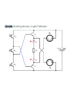
Page 94: ...Circuit Braking Mode Light Follower FT2 FT3 FT1 T2 T1 L2 L1 M2 M1 R Bat 9 V...


