Connection of the Motors
varikabi moves with the help of two
particularly slow and quiet DC motors. With
the black rubber caps varikabi therefore
requires neither a gear nor wheels.
The speed of the motors is set by the level
of the applied voltage. This voltage is
controlled with the help of the transistors or
the sensors respectively.
Depending on which transistor (T
2
, T
1
) drives
which one of the motors (M
2
, M
1
), the
following behaviors arise:
The following diagram shows how the
cables are to be mounted in the rows + 2 8
–. Depending on the selected function,
connect the motor cables as light or shadow
follower.
Light Follower:
red cables are inside
Shadow Follower: red cables are outside
The rotation direction of the motors depends
on the polarity of the applied voltage. In
order for varikabi's engines to spin forward,
make sure that the red connections always
cross and the black ones run parallel.
Note:
By connecting the motors di
ff
erently,
you determine whether varikabi will be
driving toward the dark or the light.
T
2
M
2
T
1
M
1
Light Follower
T
2
M
2
T
1
M
1
Shadow Follower
Summary of Contents for varikabi
Page 1: ......
Page 7: ...The seven varikabi models...
Page 8: ...The components...
Page 9: ...varikabi as a Dog...
Page 10: ...1...
Page 11: ...2...
Page 12: ...3...
Page 13: ...4...
Page 14: ...5...
Page 15: ...6...
Page 16: ...7...
Page 17: ...varikabi as a Sea Lion...
Page 18: ...1...
Page 19: ...2...
Page 20: ...3...
Page 21: ...4...
Page 22: ...5...
Page 23: ...varikabi as a Frog...
Page 24: ...1...
Page 25: ...2...
Page 26: ...3...
Page 27: ...4...
Page 28: ...5...
Page 29: ...varikabi as a Bird...
Page 30: ...1...
Page 31: ...2...
Page 32: ...3...
Page 33: ...4...
Page 34: ...5...
Page 35: ...varikabi as a Giraffe...
Page 36: ...1...
Page 37: ...2...
Page 38: ...3...
Page 39: ...4...
Page 40: ...5...
Page 41: ...6...
Page 42: ...7...
Page 43: ...varikabi as a Mouse...
Page 44: ...1...
Page 45: ...2...
Page 46: ...3...
Page 47: ...4...
Page 48: ...5...
Page 49: ...6...
Page 50: ...7...
Page 51: ...varikabi as a Beetle...
Page 52: ...1...
Page 53: ...2...
Page 54: ...3...
Page 55: ...4...
Page 56: ...5...
Page 57: ...6...
Page 58: ...7...
Page 59: ...8...
Page 60: ...varikabi Fischertechnik...
Page 61: ...The components...
Page 62: ...1...
Page 63: ...2...
Page 64: ...3...
Page 65: ...4...
Page 84: ...Acceleration Mode Breaking Mode...
Page 86: ...Light Follower Shadow Follower Caution The red cables are crossed connected...
Page 91: ...Circuit Acceleration Mode Shadow Follower FT2 FT3 FT1 T2 T1 L2 L1 M2 M1 R Bat 9 V...
Page 92: ...Circuit Acceleration Mode Light Follower FT2 FT3 FT1 T2 T1 L2 L1 R Bat 9 V M2 M1...
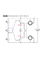
Page 93: ...Circuit Braking Mode Shadow Follower FT2 FT3 FT1 T2 T1 L2 L1 M2 M1 R Bat 9 V...
Page 94: ...Circuit Braking Mode Light Follower FT2 FT3 FT1 T2 T1 L2 L1 M2 M1 R Bat 9 V...


