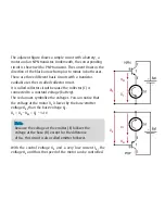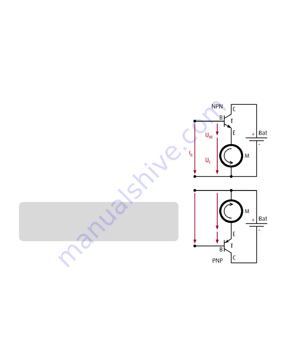
The adjacent figure shows a simple circuit with a battery, a
motor and an NPN transistor. Underneath, the corresponding
circuit is shown with a PNP transistor. The current
fl
ows in the
direction of the black arrow from plus to minus in both cases.
There are three di
ff
erent basic circuits with a transistor.
varikabi uses the so-called collector circuit.
It is called collector circuit because the collector (C) is
connected to a constant voltage (battery).
The red arrows symbolize the voltages. You can notice that
the voltage at the motor U
E
is lower by the base-emitter
voltage U
BE
than the base-voltage U
B
.
U
E
= U
B
– U
BE
= U
B
– 1.4 V
U
BE
U
B
U
E
Note:
Because the voltage at the emitter (E) follows the
voltage at the base (B) except for the di
ff
erence
of U
BE
, this circuit is also called emitter follower.
With the control voltage U
B
and a very low current I
B
, the
voltage U
E
and thus the speed of the motor can be controlled.
U
E
U
B
U
BE
Summary of Contents for varikabi
Page 1: ......
Page 7: ...The seven varikabi models...
Page 8: ...The components...
Page 9: ...varikabi as a Dog...
Page 10: ...1...
Page 11: ...2...
Page 12: ...3...
Page 13: ...4...
Page 14: ...5...
Page 15: ...6...
Page 16: ...7...
Page 17: ...varikabi as a Sea Lion...
Page 18: ...1...
Page 19: ...2...
Page 20: ...3...
Page 21: ...4...
Page 22: ...5...
Page 23: ...varikabi as a Frog...
Page 24: ...1...
Page 25: ...2...
Page 26: ...3...
Page 27: ...4...
Page 28: ...5...
Page 29: ...varikabi as a Bird...
Page 30: ...1...
Page 31: ...2...
Page 32: ...3...
Page 33: ...4...
Page 34: ...5...
Page 35: ...varikabi as a Giraffe...
Page 36: ...1...
Page 37: ...2...
Page 38: ...3...
Page 39: ...4...
Page 40: ...5...
Page 41: ...6...
Page 42: ...7...
Page 43: ...varikabi as a Mouse...
Page 44: ...1...
Page 45: ...2...
Page 46: ...3...
Page 47: ...4...
Page 48: ...5...
Page 49: ...6...
Page 50: ...7...
Page 51: ...varikabi as a Beetle...
Page 52: ...1...
Page 53: ...2...
Page 54: ...3...
Page 55: ...4...
Page 56: ...5...
Page 57: ...6...
Page 58: ...7...
Page 59: ...8...
Page 60: ...varikabi Fischertechnik...
Page 61: ...The components...
Page 62: ...1...
Page 63: ...2...
Page 64: ...3...
Page 65: ...4...
Page 84: ...Acceleration Mode Breaking Mode...
Page 86: ...Light Follower Shadow Follower Caution The red cables are crossed connected...
Page 91: ...Circuit Acceleration Mode Shadow Follower FT2 FT3 FT1 T2 T1 L2 L1 M2 M1 R Bat 9 V...
Page 92: ...Circuit Acceleration Mode Light Follower FT2 FT3 FT1 T2 T1 L2 L1 R Bat 9 V M2 M1...
Page 93: ...Circuit Braking Mode Shadow Follower FT2 FT3 FT1 T2 T1 L2 L1 M2 M1 R Bat 9 V...
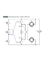
Page 94: ...Circuit Braking Mode Light Follower FT2 FT3 FT1 T2 T1 L2 L1 M2 M1 R Bat 9 V...


