The Sensors
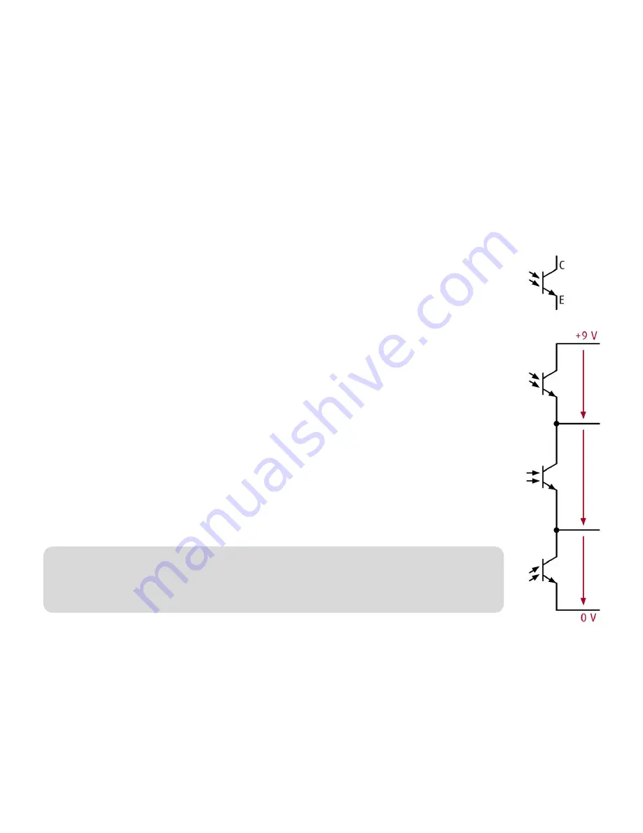
varikabi's phototransistors (FT) are similar in design to a transistor. The
collector (C) is on the plus side and the emitter (E) is on the minus side.
Instead of a basic connection, however, they have a light-sensitive area.
The incidence of light determines the permeability between the collector and
the emitter.
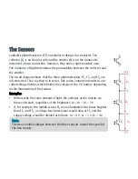
The circuit diagram shows that the three phototransistors FT
1
, FT
3
and FT
2
are
all connected. They say they're in series. This series connection results in a so-
called voltage divider, which divides the voltage of the 9 V battery depending
on the illumination of the sensors.
Examples:
•
With exactly the same amount of light, the voltages at the sensors are
three volts each, regardless of the brightness: U
2
= U
3
= U
1
= 3 V
•
If, for example, the middle sensor FT
3
were illuminated four times brighter
than FT
2
and FT
1
, a voltage four times lower would drop at FT
3
and the
supply voltage would be divided as follows: U
2
= 4 V, U
3
= 1 V, U
1
= 4 V
Note:
The two variable voltages between the three sensors control the speed of
the two motors.
FT
2
U
2
FT
3
U
3
FT
1
U
1
Summary of Contents for varikabi
Page 1: ......
Page 7: ...The seven varikabi models...
Page 8: ...The components...
Page 9: ...varikabi as a Dog...
Page 10: ...1...
Page 11: ...2...
Page 12: ...3...
Page 13: ...4...
Page 14: ...5...
Page 15: ...6...
Page 16: ...7...
Page 17: ...varikabi as a Sea Lion...
Page 18: ...1...
Page 19: ...2...
Page 20: ...3...
Page 21: ...4...
Page 22: ...5...
Page 23: ...varikabi as a Frog...
Page 24: ...1...
Page 25: ...2...
Page 26: ...3...
Page 27: ...4...
Page 28: ...5...
Page 29: ...varikabi as a Bird...
Page 30: ...1...
Page 31: ...2...
Page 32: ...3...
Page 33: ...4...
Page 34: ...5...
Page 35: ...varikabi as a Giraffe...
Page 36: ...1...
Page 37: ...2...
Page 38: ...3...
Page 39: ...4...
Page 40: ...5...
Page 41: ...6...
Page 42: ...7...
Page 43: ...varikabi as a Mouse...
Page 44: ...1...
Page 45: ...2...
Page 46: ...3...
Page 47: ...4...
Page 48: ...5...
Page 49: ...6...
Page 50: ...7...
Page 51: ...varikabi as a Beetle...
Page 52: ...1...
Page 53: ...2...
Page 54: ...3...
Page 55: ...4...
Page 56: ...5...
Page 57: ...6...
Page 58: ...7...
Page 59: ...8...
Page 60: ...varikabi Fischertechnik...
Page 61: ...The components...
Page 62: ...1...
Page 63: ...2...
Page 64: ...3...
Page 65: ...4...
Page 84: ...Acceleration Mode Breaking Mode...
Page 86: ...Light Follower Shadow Follower Caution The red cables are crossed connected...
Page 91: ...Circuit Acceleration Mode Shadow Follower FT2 FT3 FT1 T2 T1 L2 L1 M2 M1 R Bat 9 V...
Page 92: ...Circuit Acceleration Mode Light Follower FT2 FT3 FT1 T2 T1 L2 L1 R Bat 9 V M2 M1...
Page 93: ...Circuit Braking Mode Shadow Follower FT2 FT3 FT1 T2 T1 L2 L1 M2 M1 R Bat 9 V...
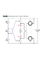
Page 94: ...Circuit Braking Mode Light Follower FT2 FT3 FT1 T2 T1 L2 L1 M2 M1 R Bat 9 V...


