background image

Formular-Nr.:51   Rev.-Nr.:10   01/18


- 11 - 

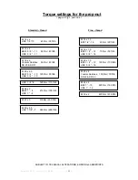
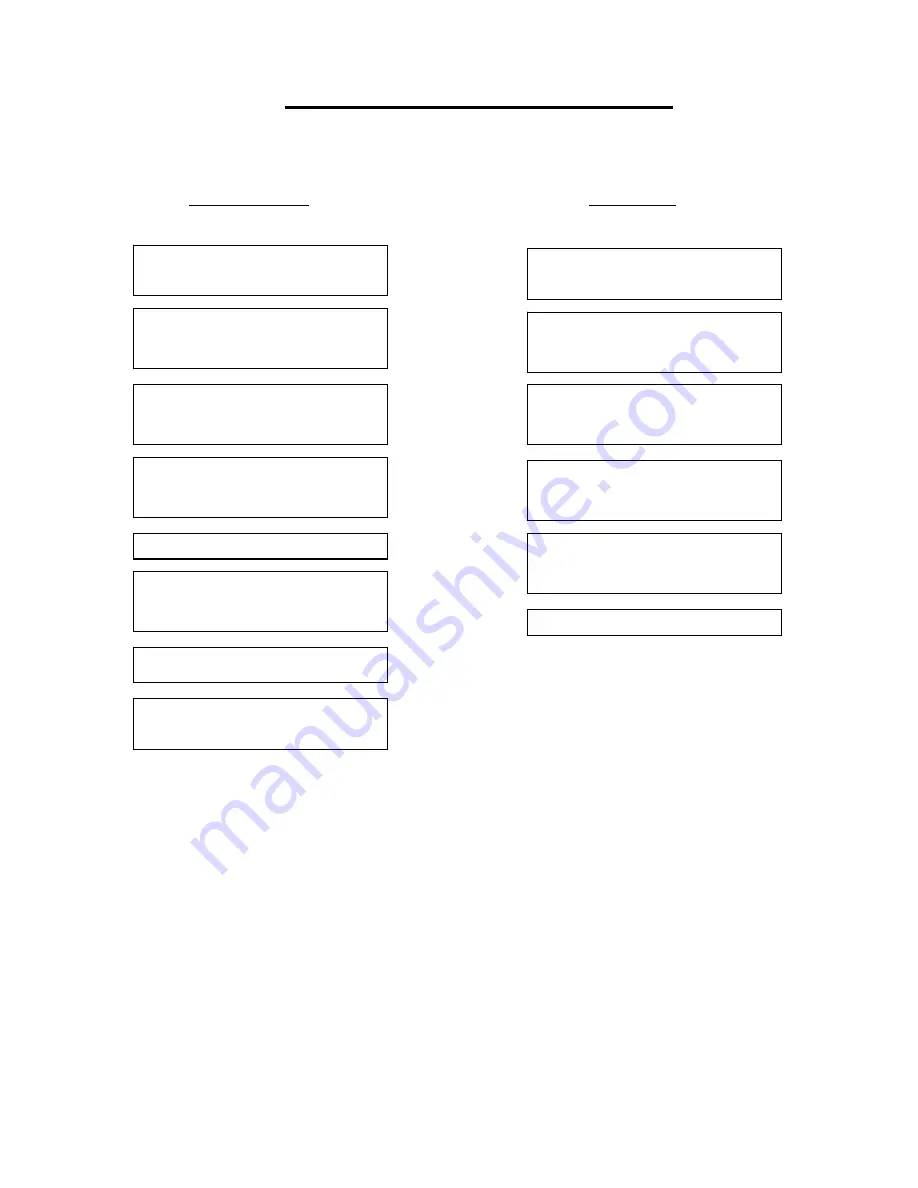
Torque settings for the prop-nut 

( page 2, Fig.1, part-no.4 ) 


Standard – thread


Fine – thread 


SUBJECT TO TECHNICAL ALTERATIONS; ERRORS and MISPRINTS 

M 16 x 2 
BSW 5 / 8 “ – 11      60 Nm / 45 ft/lb 
UNC 5 / 8 “  - 11


M 14 x 2 
UNC 1/2 “-13          40 Nm / 30 ft/lb 

M 20 x 2,5 
BSW 3 / 4 “ – 10    125 Nm / 95 ft/lb 
UNC 3 / 4 “  - 10


M 24 x 3 
BSW 1 “ - 8 

     210 Nm / 155 ft/lb 

UNC 1 “  - 8


M 14 x 1,5 
BSF 1/2 “- 16         40 Nm / 30 ft/lb 

M 16 x 1,5 
BSF 5 / 8 “ – 14        70 Nm / 50 ft/lb 
UNC 5 / 8 “ - 18


M 20 x 1,5 
BSF 3 / 4 “ – 12      135 Nm / 100 ft/lb
UNC 3 / 4 “ - 16


M 24 x 2 
BSF 1 “ - 10 

     225 Nm / 165 ft/lb

UNF 1 “ - 12


M 27 x 3 

     315Nm / 230 ft/lb

UNC 7 / 8 “-9       160 Nm / 115 ft/lb 

M 30 x 2

     430 Nm / 315 ft/lb

M 30 x 3,5 


UNC 1 1/8”  - 7      350 Nm / 255 ft/lb


M 20 x 2 
Yanmar Saildrive    100 Nm / 75 ft/lb 
SD 40 & SD 50


M 16 x 2 
Yanmar Saildrive     60 Nm / 45 ft/lb 
SD 20 & SD 31


Summary of Contents for DF-80

Page 1: ...on the Saildrive page 3 Operation page 4 Pitch adjustment LH left hand rotation propeller page 5 Pitch adjustment RH right hand rotation propeller page 6 Defining and checking adjustments page 7 Remov...

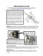
Page 2: ...the VARIPROP is fitted onto the shaft The VARIPROP needs water pressure on the blades otherwise the prop could be damaged Before fitting the VARIPROP onto the shaft check key and keyway in the propel...

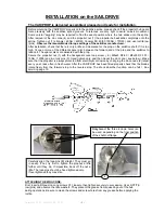
Page 3: ...avoid on axis movement Some careful wiggling may be required to find the exact position where the hub slides unto the spline After removal ot the zinc cone 4 and the propeller nut 1 the propeller hub...

Page 4: ...actuating lever between the neutral position and end positions for forward and reverse can be found in the owners manual of your transmission A larger amount of lever travel is in no way detrimental...

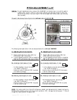
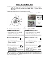
Page 5: ...or R with the 5mm Allen key as follows 2a Increasing of pitch approx 3 max 2a Increasing of pitch approx 2 max Turn the adjusting screw 2 clockwise Turn the adjusting screw 4 anti clockwise see NOTE a...

Page 6: ...R with the 5mm Allen key as follows 2a Increasing of pitch approx 3 max 2a Increasing of pitch approx 2 max Turn the adjusting screw 2 clockwise Turn the adjusting screw 4 anti clockwise see NOTE and...

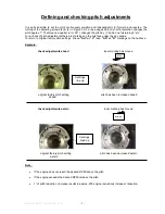
Page 7: ...ub face under the zinc anode To return to original factory pitch settings line up AH or V resp AS or R markings on the hub face Example check adjustments ahead inner marking has moved original factory...

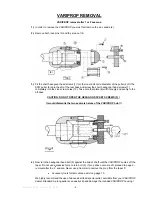
Page 8: ...6 will fit snugly and evenly to the aft boss CAUTION DO NOT OPEN THE HEXAGON SOCKET SCREWS 5 It would dismantle the two separate halves of the VARIPROP hub 4 Now turn the hexagonal head bolt 9 against...

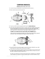
Page 9: ...ly to the aft boss CAUTION Do not dismantle the two separate halves of the VARIPROP hub In this mode remove the last hexagonal socket screw 5 as well and fit the third long hexagonal head screw Take c...

Page 10: ...y turning at the absorber area is normal and necessary for the function Make sure that you always keep the zinc anode in good condition The VARIPROP must be protected by a lot of zinc so also use a zi...

Page 11: ...125 Nm 95 ft lb UNC 3 4 10 M 24 x 3 BSW 1 8 210 Nm 155 ft lb UNC 1 8 M 14 x 1 5 BSF 1 2 16 40 Nm 30 ft lb M 16 x 1 5 BSF 5 8 14 70 Nm 50 ft lb UNC 5 8 18 M 20 x 1 5 BSF 3 4 12 135 Nm 100 ft lb UNC 3...

Reviews: