Pompa ad ingranaggi - Serie GS, GK
Gear pump - GS, GK Series
47
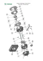
c) Replacing bearing bushes (see Figure 1)
Proceed as described at points a), b), c), e).
d1) To replace the self-lubricating supporting bushes
9
, bend them with a chisel or similar,
paying attention not to damage the diameter of the bushing seats and remove them. Before
inserting the new bushings, clean accurately the seat with alcohol to remove all impurities
and wipe them very well. Insert the new bushings
9
, which have to be slightly forced into
their seats, to the stop beat.
d2) To replace the graphite bearing bushes
9
A, it is necessary to break them with a chisel
or other convenient tool, by paying great attention not to damage the seat diameter of bush-
es and their base plane. Before inserting new bushes
9
A, clean very carefully bush seats
with alcohol in order to remove all impurities and dry well. Fit new bushes by spreading a
layer of glue of “LOCTITE 648” type over their outer diameter, by paying attention that the
bushes match perfectly each other. Then, let glue dry for about 10
÷
15 minutes.
For assembly, follow the instructions at points e), c), b), a).
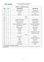
d) Replacing gears and shafts (see Figure 1)
Carry out the same operations as indicated in items a), b), c). Loosen the socket screws
?
which fasten the rear cover
4
and remove this last, by keeping into account that the opera-
tion may become difficult for the accuracy of shafts and dowel pins
A
. Draw a reference
mark on the main body
3
to avoid reversing base planes on reassembly and remove it to-
gether with the 2 O-rings
I
; the operation may become difficult for the accuracy of shafts
and dowel pins
A
. Remove the driven shaft
6
and then, after removing the seeger ring
I
B,
remove the driving shaft
5
. Extract the gears
7
and
8
from shafts, remove the feather
keys
F
and the locking spring clips
I
, if any (only for GS 34-1/48-1, GK 34-1/48-1); on re-
assembly, pay attention not to modify the position of the helicoidal tooth gears, in order not
to reverse the axial thrust direction.
On reassembly, reverse the procedure, by taking as reference the position of covers with re-
spect to the main body, the position of dowel pins and internal drain lines holes. Tighten the
screws
?
which fasten covers in a cross-wise way, by rotating at the same time the motor
shaft, so as to avoid differentiated pressures on gears, which might increase frictions. With
regard to tightening torques, please refer to point 4.6.3. Then proceed as described at points
c), a).
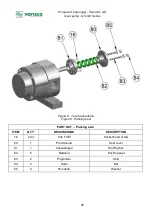
e) Safety valve replacement (see Figure 6)
Unscrew the cap
m
and remove the external sealing washer
o
. Move the nut
p
and un-
screw completely the adjusting screw
n
, paying attention to the thrust exerted by the spring
q
; disassemble the internal sealing washer
o
.
Remove the spring
q
with the shutter assembled
r
.
During re-assembly check the correct coupling between the shutter
r
and the seat obtained
in the rear cover
l
of the pump and replace both sealing washers
o
.
Summary of Contents for GS Series
Page 2: ...Pompa ad ingranaggi Serie GS GK Gear pump GS GK Series PAGINA BIANCA BLANK PAGE...
Page 52: ...Pompa ad ingranaggi Serie GS GK Gear pump GS GK Series 52...
Page 54: ...Pompa ad ingranaggi Serie GS GK Gear pump GS GK Series 54...
Page 69: ...Pompa ad ingranaggi Serie GS GK Gear pump GS GK Series 69 PAGINA BIANCA BLANK PAGE...
Page 70: ...Pompa ad ingranaggi Serie GS GK Gear pump GS GK Series 70 PAGINA BIANCA BLANK PAGE...
Page 71: ...Pompa ad ingranaggi Serie GS GK Gear pump GS GK Series 71 PAGINA BIANCA BLANK PAGE...


