9
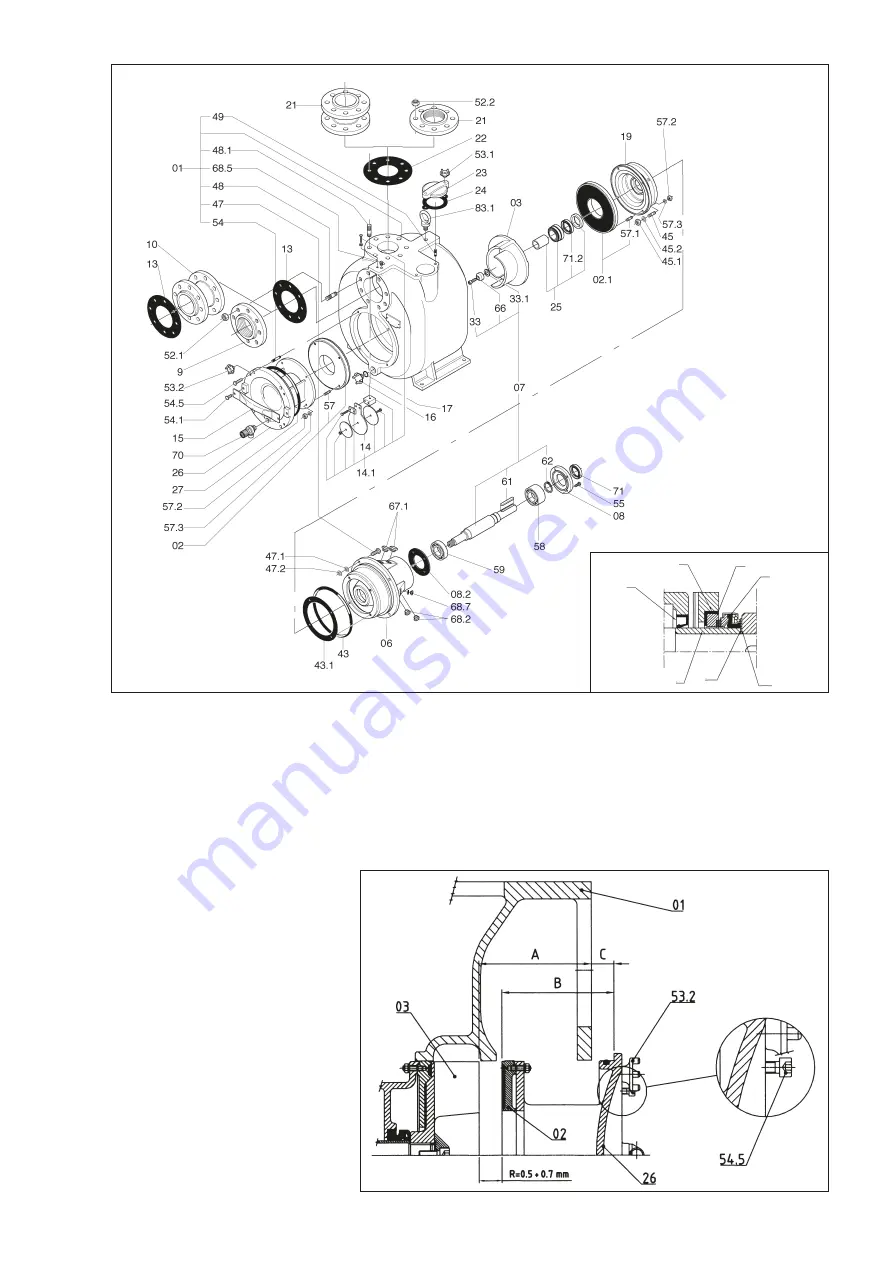
13.7 Impeller positioning with respect to wear plate(s) (fig. 11)
In all models, the distance between the tip of the impeller blades (03) and surface of the wear plate (02) must be in the range 0.5 - 0.7 mm.
To achieve this value, you need to move wear plate (02) away from the impeller (03) by turning the screws (54.5) once you have calculated
"C" as described below.
C = (B-A+R)
Where A = distance between impeller (03) and machined surface of the casing (01)
B = distance between wear plate (02) and machined surface of the inspection cover (26)
R = distancing value adopted in the range 0.5-0.7 mm
Generally, when "C" has a value of 1 mm,
the distancing value "R" will be 0.5 mm.
Tightening the screws (54.5) moves the cover
(26) away from the casing (01).
N.B.
: This operation must be performed with
the bolts (53.2) loosened.
Once the right distance "R" between the
impeller (03) and wear plate (02) has
been reached, retighten the bolts (53.2).
fig. 9
fig.10
fig. 11
41
38
39
40
25.2
25.1
31


