background image


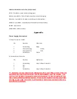
BEFORE YOU START, READ THESE WARNINGS 

1)


NEVER PLUG POWER DEVICES OTHER THAN THOSE SUPPLIED BY 
VARIZOOM INTO THE SYSTEM. ONLY USE VARIZOOM POWER SOURCES 
AND CABLES. USING DIFFERENT POWER COMPONENTS CAN LEAD TO 
SEVERE DAMAGE TO THE HEAD AND EVEN THE CAMERA. THIS TYPE 
OF DAMAGE IS NOT COVERED UNDER WARRANTY. 

2)


DO NOT MODIFY THE SUPPLIED CABLES OR ATTEMPT TO 
DISASSEMBLE THE HEAD. 

3)


LENS CONTROL CABLES MUST ONLY BE PLUGGED INTO THE 
SPECIFIED INPUT JACK ON THE LENS ITSELF – NEVER PLUG A 12-PIN 
CONNECTOR ON A VARIZOOM LENS CONTROL CABLE INTO THE 12PIN 
JACK ON THE CAMERA BODY. WHEN IN DOUBT, CONSULT VARIZOOM 
OR YOUR LENS MANUAL.  

4)


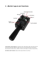
THE ADVANCED CONTROLLER DOES NOT REQUIRE SEPARATE POWER, 
IT RECEIVES POWER THROUGH THE GREEN-CODED CONTROL CABLE 
THAT CONNECTS TO THE HEAD.  THE “AUX” POWER JACK ON THE 
ADVANCED CONTROLLER IS ONLY UTILIZED IN WIRELESS 
CONFIGURATIONS AND SHOULD ONLY BE CONNECTED TO A 
VARIZOOM POWER SUPPLY. 

5)


DO NOT OPERATE THE HEAD WITH AN UNBALANCED LOAD (i.e., with 
the camera’s weight extremely off-center either horizontally or 
vertically). 

6)


DO NOT GET THE SYSTEM WET – IT IS NOT WATERPROOF. 

7)


ALWAYS MAKE SURE YOUR LENS AND POWER CABLES HAVE ENOUGH 
SLACK RUNNING THROUGH THE TILT AXIS TO PREVENT TWISTING 
AND TEARING OF THE CABLES. 

8)


MAKE SURE YOUR LENS CLEARS THE BASE OF THE HEAD WHEN 
TILTING. IF THE LENS DOES NOT CLEAR THE BASE, SET SOFT LIMITS 
(SECTION 7) TO PREVENT THE LENS FROM STRIKING THE BASE OF 
THE HEAD WHEN TILTING. 

9)


WHEN USING THE CP JR’s ONBOARD LENS CONTROLS TO CONTROL 
YOUR CAMERA, ALWAYS POWER THE CAMERA UP LAST. OTHERWISE, 
THE RECORD START/STOP FEATURE MAY FALL OUT OF SYNC. TO 
AVOID THIS ISSUE, JUST MAKE SURE TO CONNECT XLR POWER TO 
THE HEAD 

BEFORE

 YOU TURN YOUR CAMERA ON. 

Summary of Contents for Cinema Pro-K5

Page 1: ...Cinema Pro K5 Operations Manual...

Page 2: ...ECTS TO THE HEAD THE AUX POWER JACK ON THE ADVANCED CONTROLLER IS ONLY UTILIZED IN WIRELESS CONFIGURATIONS AND SHOULD ONLY BE CONNECTED TO A VARIZOOM POWER SUPPLY 5 DO NOT OPERATE THE HEAD WITH AN UNB...

Page 3: ...ncert with two optional control input devices Pan Bars for broadcast style operation or Hand Wheels for cinema style operation The Jibstick remote is a simpler less expensive controller designed for o...

Page 4: ...the tilt arm on Cinema Pro head Connect camera power if applicable between the 2 pin LEMO connector also located on the back of the tilt arm Connect the bloop sync if applicable between the camera and...

Page 5: ...m should stay level With smaller cameras under 10lbs you may not need to adjust the vertical balance For larger cameras you may want to adjust it for optimal performance and to minimize the effort the...

Page 6: ...ication cable to the green connector on the CinemaPro Head This cable runs communication as well as power so make sure that there is XLR power connected to the CinemaPro Pan direction and Tilt directi...

Page 7: ...all soft limits and then try again 3 Power down the system unplug the XLR connector wait for a few seconds re plug everything back in power it back up then try again Pan and Tilt moves too slowly or...

Page 8: ...available to join the cables Cinema Pro XLR power cables are available in 30 or 75 increments 2 head extension blocks are available and will increase the underslung clearance range from 16 5 18 5 to 1...

Page 9: ...th 6 Weight 21 lbs Maximum speed 210 deg sec max up to 512 deg sec with custom high speed motors Underslung Camera Clearance for Standard Head 15 5 17 5 camera platform adjusts 2 up down Underslung Ca...

Page 10: ...onnectors Head power 4pin XLR Kuper Node 6pin LEMO red Controller 7pin LEMO green Video out BNC Tilt arm connector front Lens control 16pin LEMO orange Tilt arm connectors back Video in BNC Bloop sync...

Page 11: ...or 1 Camera Neg Black 2 Cinema Pro Neg White 3 Cinema Pro Pos Red 4 Camera Pos Green 2 Camera Power Connector Pin Function Destination 1 Camera Neg Loop to Power Connector 2 N C 3 N C 4 Camera Pos Loo...

Page 12: ...Violet Power to Remote or Jibstick 2 Kuper Node Connector red LEMO EGG1B306CLL Pin Function DB9 1 Common 1 2 N C 3 RS 422 RXD Kuper 8 4 RS 422 RXD Kuper 9 5 RS 422 TXD Kuper 5 6 RS 422 TXD Kuper 6 3 O...

Page 13: ...B302CLL Pin Function 1 Camera Power 2 Camera Power 2 Sync Bloop Fischer D103A056 130 Pin Function 1 Common Iso 2 5 VDC Iso 3 Sync In 5 Bloop Out 1 6 Bloop Out 2 2 Camera Control white LEMO EGG2B312CLL...

Page 14: ...n Lens Connection 1 RS 232 RXD Fuji Digital 2 RS 232 TXD Fuji Digital 3 5 VDC Iso Fuji Digital 4 Common Iso Fuji Digital 5 RS 422 RXD Canon Digital 6 RS 422 RXD Canon Digital 7 RS 422 TXD Canon Digita...

Page 15: ...c 4 4 IsoCom IsoCom3 5 19 20 Green 5 RS 422 RXD 17 Orange 6 RS 422 RXD 18 Yellow 7 RS 422 TXD 15 Brown 8 RS 422 TXD 16 Red 9 Common 2 3 20 10 Vcc 5 volts 11 Analog 1 out 7 If zoom 9 Zoom 2 12 Analog 2...

Page 16: ...al Connector gray EGG1B308CLL Pin Function 1 Common 2 1 RS 232 RXD 3 1 RS 232 TXD 4 5 VDC 5 24 VDC 6 2 RS 232 RXD 7 2 RS 232 TXD 8 24 VDC 3 ANALOG Panbars Option Zoom and Focus Control Input white EGG...

Page 17: ...tick Connectors 1 Cinema Pro Control Green LEMO EGG1B307CLL Pin Function Wire Color Cable 1 Common Brown 2 RS 422 RXD Red 3 RS 422 RXD Orange 4 RS 422 TXD Yellow 5 RS 422 TXD Green 6 24 VDC Blue Power...

Reviews: