3
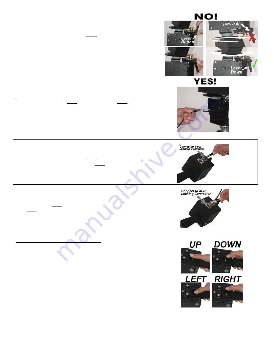
5. Engage the brass motor gears to the black arm gears and tighten.
Be sure the levers are pointing away from the rotating arm.
-NOTE: Once tightened, you can adjust the position of the lever by
simply pulling out on it and then rotating the lever until it faces away.
This will NOT loosen the fastener.
Failure to aim lever away will
impede the movement of the MC100.
Connecting the Cables
1.
Connect the locking 4-pin control cable to the 4-pin motor cord at the
base of the MC100.
2.
Connect the other end of the 4-pin control cable to the
MC100 Control Unit at the locking 4-pin connector.
3.
Connect the 4-pin XLR power cable from the AC adapter to the
4-pin XLR power connector located on the MC100 Control Unit.
OPERATION OF MC100 CONTROL UNIT
1.
The joystick controls camera movement in a fashion similar to airplane
controls. Joystick Forward: camera points down; Joystick Backward:
camera points up; Joystick Left: camera points to the left; Joystick Right:
camera points to the right. (assuming the silver toggle switch is in the
normal position – to the left).
*NOTE: The UP/DOWN joystick directions will depend on how the
camera is mounted – you can reverse the UP/DOWN by turning the
camera 180 degrees to face the opposite direction. For normal operation,
mount the camera so that the left side (viewfinder/LCD panel side) faces
out away from the rotating arm.


