18
Värmebaronen EP 26E and EP 42E
11
21
31
12
22
24
32
RE1 RE2
RE3 RE4
11
21
31
12
22
24
32
K1
N L1 L2 L3
A1
A2
N
N
F
CP
2
1
RE1
RE2
RE3
ALARM
C-PUMP
N
(clean)
3
2
4
1
1
2 3
4
5
1
2
4
1 2 3 4
3
K1
Line
Load
N
N
(clean)
N
(clean)
RE4
6A
L2
L3
T1
T2
T3
L1
V
m
V
m
A
m
A
m
N
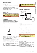
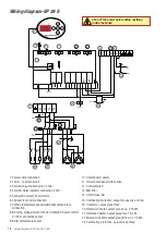
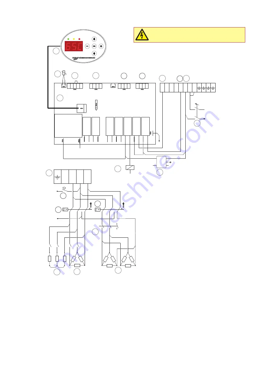
Wiring diagram-EP 26 E
Shut off the power before doing anything
inside the boiler!
2
4
1
9
13
12
19
5
3
14
6
8
21
22
15
24
10
7
11
20
19
1. Power cable connection.
2. 230V ~, to external unit.
3. Circulation pump connection, 230V~.
4. External alarm indicator connection, 230V ~.
5. Connection current transformers.
6. Optional room unit connection.
7. Outside temperature sensor/alternative temperature
connection.
8. Blocking, voltage/current control, limitation/Output control,
0-10V of connected output
9. Boiler temperature sensor.
10. Circuit board, power
11. Circuit board panel with overlay.
12. Control switch.
13. EMI filter
14. Control fuse, 6A.
15. Overheating protection, output groups one and two.
19. Contactor, output group three.
20. Immersion heater, output group one, 3.75 kW.
21. Immersion heater, output group two, 7.5 kW.
22 Immersion heaters output group three, 2 x 7.5 kW.
24. Overheating protection, output group three.

