22
Värmebaronen EP 26E and EP 42E
Troubleshooting - Warning, limitation and alarms
Limitations
Reason
Explanation
Activation delay
Power-on limitation active. When boiler is restarted after power loss, it is connected
(if necessary): 1/3 of the output immediately, max 2/3 after 20 minutes and the remainder
40 minutes after power has returned.
In service mode, accelerated delay can be run. See menu item, Service level, row 2.
The time delay can also be permanently removed via menu item, Advanced Service level,
row 14.
The load guard limits
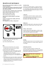
Green indicator flashes: The load guard limits.
For more information, see menu item, Installation/service level, rows 3-4.
External restriction/
blocking
Green indicator flashes: external limit.
0 – 10V on the input corresponds to 0 – 100% of installed output.
Manual operation
Manual selection to activate selected number of steps, control circulation pump and
buzzer alarm. For more information, see menu item, Advanced Service level, rows 18-22.
ECO mode
Green indicator flashes: ECO mode active.
Control function is enabled via the Menu, User level, row 12.
Warnings
The display shows current warnings if no stop alarms occur. The information remains until OK is pressed and the cause of the
warning has been resolved.
Reason
Explanation
High temperature around
the PCB.
Yellow indicator flashes: temperature above 45° C, yellow indicator goes off: temperature
below 42° C and the warning is acknowledged with OK.
Output steps down: Temperature above 55° C output steps in: Temperature below 45° C
High boiler temperature
Yellow indicator flashes: warning for overtemperature.
Yellow indicator goes off: the temperature has fallen below the limit and the warning is
acknowledged with OK.
Selectable via Menu, Advanced Service level, rows 16-17. At overtemperature, the
connected output steps out and steps in again only when the temperature has dropped
below the limit.
Low boiler temperature
Yellow indicator flashes: boiler temperature below 7° C. The boiler must always be at least
7° C during operation regardless of the specified setpoint.
If external blocking/external control is active, the boiler is NOT allowed to step in output.
If the load guard restricts, the boiler must NOT step in output.
Outdoor sensor
Yellow indicator flashes: incorrect value, interruption/short circuit on sensor and/or
disconnection of the outside sensor. Control assumes 0° C outdoor temperature.
Room sensor
Yellow indicator flashes: incorrect value, interruption/short circuit on sensor and/or
disconnection of room sensor. The room sensor is disconnected from the control until
the alarm is acknowledged and the sensor is repaired.
Room sensor, handwheel
setting
Yellow indicator flashes: incorrect value, interruption/short circuit or disconnection
of the setpoint. The room sensor is disconnected from the control until the alarm is
acknowledged and the sensor is repaired.
Stop alarm - Boiler blocked
Display shows current alarms. The information remains until the cause is corrected and OK is pressed
Reason
Explanation
Boiler temperature sensor
Red indicator flashes: incorrect value or interruption/short circuit on sensor.
Temperature sensor on
circuit board
Red indicator flashes: incorrect value or interruption/short circuit on sensor.
Low boiler temperature
Red indicator flashes: boiler is blocked at boiler temperature below 3° C.
Overheat protection is
trigged
Red indicator flashes: an alarm is blocking the boiler. All relays/contactors release,
circulation pump continues to run.
Low input voltage
Red LED flashes: excessively low supply voltage to electronics.
The relay outputs on the control are blocked.

